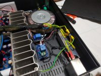
I've finished my project and in the next days I'll test more better. I've a question about ground, the pgnd must be connected? The toroidal transformer must be isolated from chassis or not? And the heatsink? ��
Heatsink, chassis and PGND all should be at the same potential. All connected.
If your transformer has a schield implemented, that one should go to PGND as well.
Otherwise the transformer must be isolated from everything else..
Ciao, George
If your transformer has a schield implemented, that one should go to PGND as well.
Otherwise the transformer must be isolated from everything else..
Ciao, George
Thanks it's greatHeatsink, chassis and PGND all should be at the same potential. All connected.
If your transformer has a schield implemented, that one should go to PGND as well.
Otherwise the transformer must be isolated from everything else..
Ciao, George
I've finished my project and in the next days I'll test more better. I've a question about ground, the pgnd must be connected? The toroidal transformer must be isolated from chassis or not? And the heatsink? ��
George's answer is correct but for PGND (IMHO, George please explain your suggestion).
To be faithfull to My_Evo Rev A recommendations PGND should be not connected, from the build guide:
The My_Ref and so the My_Ref Fremen Edition are floating designs so they’re not supposed to be grounded.
While best perceived performance is achieved without any form of grounding the resulting system would be not completely safe since in case of a catastrophic failure you could have mains voltages on connectors.
While such a fail is unlikely for a safe build which retains most if not all of its perceived performance use a safety ground loop breaker connected to PGND and safety ground, like in this suggested grounding layout:
An externally hosted image should be here but it was not working when we last tested it.
(image from Elliot Sound Products website)
Last edited:
And for the potentiometer? Which is the best value: 50kohm?
Mauro Penasa, the original designer of the My_Ref recommended 10K Log
Hi everyone, i checked my amp and i found that everything seem ok except for input gnd/0 that is on the same path of PGND, directly on the board!
By consequence, the input gnd/0 is linked to everything else, case and other channel input gnd/0 included: WHY? 😱
IS THAT RIGHT?
If not (and in my opinion should not) how to solve the problem?
By removing R11, signal ground will be divided to power ground? it's safe to remove?
I verified that input connector are insulated.
I also notice that output gnd/0 is not on the same path of PGND or imput, it's isolated.
Waiting for your reply.
Thank you very much 🙁
If you remove R11 the feedback loop is broken and the amp output will go full negative Voltage. What is the problem you are trying to fix?
What do you mean by "the same". The 1ohm resistance of R11 is doing exactly that, the separation of the two ground domains.
So you must see 1ohm between the two, not more not less.
Ciao, George
So you must see 1ohm between the two, not more not less.
Ciao, George
OK, my problem is this: input signal gnd/0 is in contact to the PGND.
I did a 'contact' test with the multimeter and there is contact!
But normaly gnd of signal should not in contatc with PGND, right?
And also, why only input gnd/0 and not output gnd/0 that is (IHMO) correctly not?
Once again and simply put: with board populated and all cable disconnected, is it ok if with multimeter i find that input signal gnd is in contact with pgnd?
If not, wich is the solution?
Thank you.
I will try to explain. The 1 ohm resistor connects input ground to power ground. The floating is the power transformer does not connect PWGD to AC ground.
Look at the power transformer wiring.
To your comments, signal and power ground are connected. Should read one ohm.
Look at the power transformer wiring.
To your comments, signal and power ground are connected. Should read one ohm.
There are two reasons for the 1 ohm resistor between input and power ground.
1. Reduces hum. Does this by bring the potential close together with some buffer.I have seen 10 ohm and even 22 ohm used in other power amplifiers.
2. Limits the current flow between the two grounds. If the impedance between the two grounds is close to zero a small voltage difference (0.0001 mv) can cause thousands of amperes to flow. Does not work that way in practice.
" I did a 'contact' test with the multimeter and there is contact!"
This is why I asked. Your multimeter whistles with 1ohm but that does not mean you have a real short..
This is why I asked. Your multimeter whistles with 1ohm but that does not mean you have a real short..
Ok, now I understand the function of 1ohm resistor between the 2 ground!!!
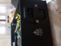
Last question: in my amp I use an IEC with EMI filter, it's OK or should EMI filter avoided in power amp like my_ref?
Thank you all and happy new year!
Last question: in my amp I use an IEC with EMI filter, it's OK or should EMI filter avoided in power amp like my_ref?
Thank you all and happy new year!
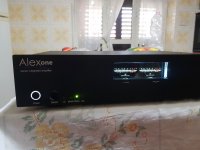
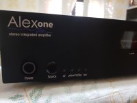
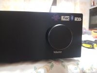
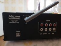
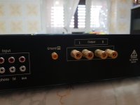
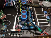
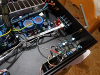
My MyRef power amplifier
Finally, after 5 months of work, the amplifier is finished. I designed the chassy and made it from "hifi2000" then in the project I inserted a LED vumeter, a motorized volume control and input selector with remote control, a bluetooth receiver with DAC BB PCM5102A to 24Bit that recognizes the input signal if it does not arrive nothing from bluetooth makes the switch with an analog input. I then inserted a USB DAC useful for connecting a PC or a multimedia player of FLAC files, and produced by ESS and is an ES9023 PCM2706 16bit / 44khz.😀
Finally, after 5 months of work, the amplifier is finished. I designed the chassy and made it from "hifi2000" then in the project I inserted a LED vumeter, a motorized volume control and input selector with remote control, a bluetooth receiver with DAC BB PCM5102A to 24Bit that recognizes the input signal if it does not arrive nothing from bluetooth makes the switch with an analog input. I then inserted a USB DAC useful for connecting a PC or a multimedia player of FLAC files, and produced by ESS and is an ES9023 PCM2706 16bit / 44khz.😀
Attachments
-
 20190129_091153.jpg194.1 KB · Views: 490
 -
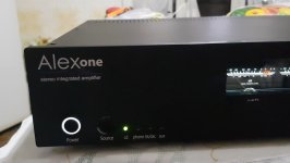 Immagine.jpg115.4 KB · Views: 475
 -
 20190129_091041.jpg139.2 KB · Views: 485
 -
 20190129_091117.jpg109.3 KB · Views: 484
 -
 20190129_085329.jpg119.1 KB · Views: 477
 -
 20190129_085333.jpg115.7 KB · Views: 256
 -
 20190129_085314.jpg125.4 KB · Views: 242
 -
 20190129_085347.jpg311.7 KB · Views: 292
 -
 20190129_085350.jpg357.5 KB · Views: 358
 -
 20190129_085405.jpg414.3 KB · Views: 361
- Home
- Amplifiers
- Chip Amps
- My_Ref Fremen Edition - Build thread and tutorial