The ESD flip is only metal at most two masks, you can stop the line and catch the stuff in process at the end (metal is last). So in these days it was a $20K - $50K loss.Chip layout errors sound expensive.
Funny anecdote, my second faculty adviser was a consultant at ADI on the side (I never knew till years later) and he came to a layout review of a knockoff of the uA741 that he had done. Well he had left off the null pins and the site manager immediately showed him the door.
I could definitely see a late metal layer being less costly, as mask resolution drops by then, greatly mitigating any nonidealities that might form from stop/start. Not likely to get too many critical defects at that point. Plus the mask itself is cheaper.
M1 wouldn't be so kind, though.
M1 wouldn't be so kind, though.
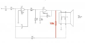
...in theory, this scheme will control the vc throughout it's working range. My prediction is that it will flatten the acoustic output response, flatten the phase, and lower distortion.. But it'd be nice to have that confirmed or shot down in flames...
In practice it has limits, and does require equalization, since it moves the
piston drive off of the "constant acceleration" paradigm, and there is
the non-trivial communication between the two voice coils.
But it's quite simple to implement, and does work pretty well for subwoofers.
Are you talking about the scheme I spoke of? Or are you talking about current drive? There's a schematic about a bazillion posts back (two days ago) that is the closest.
My scheme absolutely requires the communication between the voice coils. It depends on both coils coupling exactly the same to all the flux. It's purpose is to use the real part of the impedance of the speaker as the feedback node. That way, the amp will drive the reactance, but the fidelity will be between the input signal and the real component of the speaker response. at the driver.
edit:here is the post, I can't figure out how to copy the picture.. but I would break into the amp and use it's normal feedback.
This scheme absolutely requires a bifilar or co-wound voice coils, as it also rejects variation of vc inductance vs position, if the coils are front/back, that cannot occur.
jn
My scheme absolutely requires the communication between the voice coils. It depends on both coils coupling exactly the same to all the flux. It's purpose is to use the real part of the impedance of the speaker as the feedback node. That way, the amp will drive the reactance, but the fidelity will be between the input signal and the real component of the speaker response. at the driver.
edit:here is the post, I can't figure out how to copy the picture.. but I would break into the amp and use it's normal feedback.
Like this?
//
This scheme absolutely requires a bifilar or co-wound voice coils, as it also rejects variation of vc inductance vs position, if the coils are front/back, that cannot occur.
jn
Last edited:
Does underhung vs overhung voicecoils affect it if it does?
I would love to test the concept, if I can get a break from headphone work. Basic.tests would not be too challenging. Two or three days effort to strap everything together and get real measurements if a stock dual voicecoil driver will work.
I would love to test the concept, if I can get a break from headphone work. Basic.tests would not be too challenging. Two or three days effort to strap everything together and get real measurements if a stock dual voicecoil driver will work.
In practice it has limits, and does require equalization, since it moves the
piston drive off of the "constant acceleration" paradigm, and there is
the non-trivial communication between the two voice coils.
But it's quite simple to implement, and does work pretty well for subwoofers.
So it has been done like this?
//
Attachments
Of course, the tech I 'threatened' is my best friend, and we have known each other for 61 years now. I don't think I scared him much, as he is coming to work tomorrow.
It should not affect it. Any magnetic non linearities will be seen by both coils identically in the case of co-wound or bifilar or my interstitial scheme.Does underhung vs overhung voicecoils affect it if it does?
I would love to test the concept, if I can get a break from headphone work. Basic.tests would not be too challenging. Two or three days effort to strap everything together and get real measurements if a stock dual voicecoil driver will work.
If the coils are front/back, excursion based inductance non linearities will be worse.
Nice. I was thinking that the values might be driver dependent. As in, if the second coil opens, the resistor may have to be altered such that the acoustic power remains the same, just that the non linearities would not be compensated out. It would be nice if output stayed the relative same level for pro apps, but it might be good to have a level change indicating a break.So it has been done like this?
//
Jn
Well, that's a different story, you didn't mention that.Of course, the tech I 'threatened' is my best friend, and we have known each other for 61 years now. I don't think I scared him much, as he is coming to work tomorrow.
With my techs, if I did that to any of them, they'd tell me f you. And we'd all laugh.
Jn
Poetic licence, I'm afraid these creative types do that a lot. I have a lady friend who is creative, I asked her how much of what she says is true, she said about 50%, I said so if what you say sounds like BS it probably is? she just laughed
During WWII the Germans...
Ed that post reminded me of something I read the other day that made me think of you, as it has to do with sound reproduction in large spaces.
So in WWII the BBC broadcast their evening news program to Europe, voice of freedom and all that. The start of the evening news was always a LIVE broadcast of the tolling of Big Ben, both a time signal and a symbol. However, clever German physicists analyzed the tonality of Big Ben's bells and were able to deduce atmospheric conditions in London, and the Luftwaffe were able to make use of that intelligence in planning bombing raids. When the British military intelligence types figured it out, the BBC switched to a fixed recording of Big Ben so it always sounded the same. This was when a radio broadcast of a time signal was not simply echoing an external event, but became the actual time authority.
Hi Pavel.If you could try to replicate what they´ve done with the broadband noise source and 10 Mhz sine signal combined via a power combiner, it would be interesting.........
In my subjective experience of BQP, it seems that existing noise itself 'drives' the Bybee.
IOW the subjective 'cleansing' effect is proportional to the existing system noise AND program embedded noise with greatest effect on 'dirty' systems and lesser effect on very clean/quiet systems.
Sinewave excitation showed no solid results on some testing I tried.
One experiment that did show remarkable effect was when listening to pink noise through loudspeakers.
The 'nature/pitch/tempo' of the reproduced pink noise changed quite noticably, subjectively less disturbing and subjectively a little quieter.
Notably pink noise sounded as it should and not the bursty harsh wrongly erratic character as is normally reproduced.
BTW my PN/speaker test result was with the BQP placed against Cat 5 cable wired as paralleled pairs, ie not actually in circuit. 😱
I think you need to look also in the current noise domain, not just the voltage noise domain.
It seems that reactive loading has something to do with BQP operation and effect on systems. ....maybe.
Take a listen, a proper listen to systems with BQP in different circuit positions and this may help you you to devise a suitable measurements strategy.
Explanation of BQP device operation principle would also help to explain operation of my device.
Go to it, get some measurements and physics explanation and your rewards will be great.
Dan.
Hi Pavel.
In my subjective experience...
existing noise itself 'drives' the Bybee...
'cleansing' effect is proportional to the existing system noise...
greatest effect on 'dirty' systems...
The 'nature/pitch/tempo' of the reproduced pink noise changed...
not the bursty harsh wrongly erratic character...
current noise domain...
reactive loading has...
I guess it's true, when all you have is a hammer, everything looks like a nail. But now you have picked up the latest buzz words in this thread to decorate the same vacuum.
Max. I think you are making a serious point. That is probably why when we try to actually 'measure' the Bybee we always measure it in a way that does not 'excite' it, just because that is how normal measurements are made. Of course, I first tried to measure it back in 1995, and could find 'nothing'. However when I listened to music with it in the circuit, I could hear a difference. I trust my ears first, measurements second.
Last edited:
from the latest descriptions a simple test would be to start with a really low distortion sine wave and connect it to an analyzer with a really low noise floor. Add broadband noise (say -90 dB from the signal). Measure THD+N (all N in this case) without and then with the bybee in the circuit. The measurement will automatically correct for change in signal level. The noise floor should drop if it does what has been described. There is something similar in many DAW's, called a noise gate. . . If it just changes the noise character that should also be obvious. (My noise source is analog, no periodicity.)
This I can do pretty easily I think. Tomorrow.
This I can do pretty easily I think. Tomorrow.
Maybe an automatic signal level adjustment is problematic in a measurement situation where no distinct signal exists? Was maybe this the problem in the above lab-test? Especially if the spectral composition of the "signal" is believed to change. At least one need to decide on a reference band for level - say the audio band..?
Maybe measurements sequences like;
- DUT present w/ and w/o added N
- DUT w N, wire w N (leave everything static and fixed and just exchange DUT).
w and w/o sine?
Brodband as well as filtered for audio?
1audio - would love to see them and I'm sure you are already on top of these problems I mention!
//
Last edited:
from the latest descriptions a simple test would be to start with a really low distortion sine wave and connect it to an analyzer with a really low noise floor.
The same I have been thinking for some time, but I would add it should be a very low amplitude sine wave 24bit like -120dBFS. Normally we use such signals to test 24bit audio and normally any good 24bit audio is able to transfer the -120dBFS tone and cleanly rise from the noise floor. Will Bybees let -120dBFS or even -140dBFS sine cleanly pass through or will it consider a noise component? 😛 (Because IT IS below noise floor with 20kHz BW).
P.S.: I need to add I am NOT going to spend my time with this.
Last edited:
Hi Demian, good suggestions but maybe not quite the answer.
From subjective and measurements attempts experience you need to put known noise through a clean (THD/IMD) but excess noisy stage.
I have made the statement previously that it seems that BQP affects excess noise production, ie consequential self noise in downstream stages.
By affecting/effecting circuit excess noise production behaviour there is not modification of input/throughput signal, however the signal+noise resultant at the output of the stage will be different and no demons are violated.
FFT - YouTube
Dan.
Last edited:
Motional feedback does work with more complex acoustic loadings. But you have to soften the control (=degenerate it) properly in that frequency range so as to install the proper damping from the transducer which it applies to that resonant loadings. If your control is "too stiff", the speaker cone will be a brick-wall for any incident sound which gives the resonator Q's the value they would have if the whole driver is replaced by a rigid wall integral to the enclosure. So eg a reflex box converts to a way too narrowband high-Q Helmholtz resonator especially if the acoustic design targets for low mechanical losses. This also applies to drivers with too large internal self-regulation aka lowish Qes, actually an internal velocity control under voltage drive. We can hardly design a proper reflex with any Qts<=0.1 driver.What I'm not sure about is how this scheme would deal with a multi order speaker. Direct radiator closed box, seems a no brainer. But, T-lines, reflex to a point, 4th and 6th order bandpass, all store energy in resonant or pseudo-resonant structures, so I'm not sure how well my scheme would work on those.
Only when used in CB or open-baffle we can try implement as stiff a control as we can manage without severe acoustic alignment issues. For CBs, actually lossy (but non-radiating) enclosures are an advantage with drivers operated in a tight feedback loop.
Early example of a at least partially documented dual-VC based controlled subwoofer: http://www.macaulayaudio.co.uk/roaring sub.pdf
Last edited:
- Status
- Not open for further replies.
- Home
- Member Areas
- The Lounge
- John Curl's Blowtorch preamplifier part III