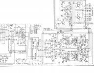
Hello all, i want to recap a vintage low wattage kenwood receiver..
i attached the schematic. i need help to identify the capacitors in the signal path...
from what i understand there are two 0.47uf caps in signal at the beginning of the power amp. these caps are tantalum...
i need help, i need to know if there is more caps in the signal so i can replace for better ones.
thanks for the help.
Attachments
Yes were all just sitting here waiting to spring into action the very second someone asks for help.
None of us have lives outside of this forum at all.
The price for the free help and information your after is Patience....
None of us have lives outside of this forum at all.
The price for the free help and information your after is Patience....
There doesn't appear to be many in the direct signal path but they all affect the signal in some way. There aren't that many so I'd probably just replace them all with some quality Nichon audio caps or Elna Silmac II's (good quality, not expensive) or your favorite audio caps, except power supply caps.
Personally I would replace the tantalums with new tantalums to retain the original sound personality. You can replace them with electrolytics if you would rather. In the case of the 0u47 input decoupling caps you could also use good non-polar electros like the green Nichon Muse or film/poly caps as well.
Make a list from the schematic or BOM of cap#, value, voltage, type & location and as you remove each one check them against your list, measure the lead spacing and write that down too. Sometimes what's on the board doesn't match the documentation. I'd match what you remove. Now you have a proper list of parts to order and a check list as you install them.
There are tons of threads on re-capping. As a beginner you would be well advised to read through as many as you can, then read read read some more. The more you know......and take your time.
Good luck.
Well, you will want to replace all the electrolytic caps. Large 30 year old electrolytics in power supplies tend to leak their guts all over the circuit board. Between Mouser.com and Digikey.com you will be able to find identical value, voltage and mechanical size replacements. Changing the few electrolytic / tantalum caps that are in the signal chain with C0G Ceramic or film caps can be done provided you can fit them in the space available.
If you are new to soldering, go get a $.50 old radio and practice removing and replacing parts before you start in on the receiver. You will want a temperature controlled soldering iron and a solder sucking tool.
If you are new to soldering, go get a $.50 old radio and practice removing and replacing parts before you start in on the receiver. You will want a temperature controlled soldering iron and a solder sucking tool.
Thks i know how to solder.. my concern is that i don t understand what caps are on signal path beside the 2 tantaluns on the power amp...
I understand the part of the power supply etc.. but not the transistor part... lol
There is a lot of resistors in signal i supose..
I understand the part of the power supply etc.. but not the transistor part... lol
There is a lot of resistors in signal i supose..
If they're electrolytic, replace them. if they're tantalum, replace them with an electrolytic. If they're anything else, leave them alone.
The electrolytics/tants that are in the signal path are: Ce3-6, Ce9-12, Cd13-14, Cd17-20, Cd25-26
Some of the small values such as the 6.8u 10v parts could be replaced by Wima MKS2 film capacitors, if they will physically fit. Similarly there are some capacitors in series e.g. Cd17/19, and Cd18/20, which you could replace with a single nonpolarised capacitor of better quality. However if you are unsure of your skills, just replace like for like with good quality electrolytics.
Ce3 and Ce4 could be 1uF capacitors without any problems, in fact it would extend the lower end response a bit
In general, if it goes between the power rail and ground, not signal path. Everything else, signal path.
Tks for the help..If they're electrolytic, replace them. if they're tantalum, replace them with an electrolytic. If they're anything else, leave them alone.
The electrolytics/tants that are in the signal path are: Ce3-6, Ce9-12, Cd13-14, Cd17-20, Cd25-26
Some of the small values such as the 6.8u 10v parts could be replaced by Wima MKS2 film capacitors, if they will physically fit. Similarly there are some capacitors in series e.g. Cd17/19, and Cd18/20, which you could replace with a single nonpolarised capacitor of better quality. However if you are unsure of your skills, just replace like for like with good quality electrolytics.
Ce3 and Ce4 could be 1uF capacitors without any problems, in fact it would extend the lower end response a bit
On dac circuits etc i understand that but in this schematic is a bit confusing...In general, if it goes between the power rail and ground, not signal path. Everything else, signal path.
For example ce5 and ce6 ?
Cd17/19, and Cd18/20 are tantaluns.. so i can replace with a nichicon muse bipolar for example. There are some mylar caps i was thinking switch to film caps...
And the smaller values are ceramics i think i can replace with cogs.
And the smaller values are ceramics i think i can replace with cogs.
Cd13, Cd14, Cd25, Cd26 may be bi-polar. Hard to read the schematic but they appear to have different markings and do not have a + sign. Just check what is installed and if they are bi-polar use Nichicon ES for those.
IMO use Elna Silmic II to replace all electrolytic or tantalum previously identified as signal-path. The only exception, optionally, is Ce3 & Ce4 which could be 1uF (or .47) Wima MKS2 as already mentioned. For non-signal path use Panasonic FC.
Don't worry about changing out mylar or ceramics.
Which Kenwood model is this?
Last edited:
i made a list on the tone control section (bass and treble pots):
one channel list:
Cd26 6.8uf electrolic non polar - change to nichicon muse or wima mks
Cd14 6.8uf electrolic non polar - change to nichicon muse or wima mks
Cd18/Cd20 3.3 two tantalum in series - change to two wimas mks or jus one 1.5uf or 1.6 uf from other brand but will not have the same value that is i think 1.65uf for the two caps in series ( i don´t know if is critical)
Cd16 Mylar 0.22uf - change to wima mks or fkp
Cd22 Mylar 0.033uf - change to wima mks or fkp
Cd24 Mylar 0.15uf - change to wima mks or fkp
i could stay with the original Mylar as roger2 suggested
Last edited:
I downloaded a good copy of the Service Manual and took a closer look. I recommend getting a copy from the link titled "service manual (alt scan)" by jwscottjr on the the page linked below. It is a better scan than the other one there. Plus it has the power supply rails marked so it is easier to see what is going on.
Kenwood KR-2400 - Manual - AM/FM Stereo Receiver - HiFi Engine
the parts I would use if I was restoring this amp are listed below...
Main Amp
Ce3,4 I would use Wimas. The originals are tantalum which is lower leakage (as are Wima films) than electrolytic. Original .47uF is OK, or could use .68uF or 1uF
Ce23,24 are bipolar, I would use Nichicon ES.
Ce21,22 are rail-to-ground (not signal path). I would use Panasonic FC. But Elna Silmic II would be OK as well.
NFB (negative feedback loop) is a good candidate for improved parts. I would replace Re15,16 with good quality metal film with temperature coefficient 50ppm or less (Vishay Dale CMF or less expensive TE LR1). And Ce5,6 I would use Nichicon ES bipolar. For both the cap and resistors mentioned above, you will want to check physical sizes of potential replacements vs available board space. You can increase voltage rating of the ES caps if space will allow.
Everywhere else in the main amp Elna Silmic II to replace electrolytics.
Not necessary, but if you really want to replace some ceramics, Ce7,8 would be the candidates most likely to possibly do any good.
I wouldn't worry about any of the mylars or other ceramics.
Tone Control Section
In this amp the NFB is routed through the tone controls. Best possible caps here could make an audible improvement.
If space allows, Cd13,14 & Cd25,26 should be Wimas. But 6.8uF Wimas will be larger than the originals. If they won't fit then use Nichicon ES.
Cd17-20, those back-to-back pairs, were originally tantalum according to the parts list. Tantalum might have been chosen here for its low leakage properties (vs electrolytic), I don't know. But I would make every effort to use Wimas here instead of Nichicon ES. Again, this whole tone section is part of the NFB which plays a critical role in the sound of the amp.
If you replace each back-to-back pair with one Wima, the empty positions on the PCB should be jumpered.
***One thing that I am uncertain about, is what uF value should be used here to replace the original, back-to-back, 3.3uF polarized tantalums. Electrolytics wired back-to-back give a total uF that is 1/2 of each cap's value. Not sure if it works the same way with tantalums***
RE Wima caps
MKS2 is not the only series of Wima polyester caps available. It is the most popular. MKS2 all have 5mm lead spacing (as far as I know). If needed, there are some 2.5mm lead spacing Wimas available in the MKS series.
Good luck with your project
Last edited:
I missed the phono section. It is separate from the tone section on the schematic even though, apparently, they are on the same PCB.
Cd1,2 Wima if they will fit. Silmic II otherwise. (direct signal path)
Cd3,4 Silmic II
Cd11,12 Panasonic FC (power supply)
Cd1,2 Wima if they will fit. Silmic II otherwise. (direct signal path)
Cd3,4 Silmic II
Cd11,12 Panasonic FC (power supply)
I downloaded a good copy of the Service Manual and took a closer look.
Thank you very much Roger for you help,
i did not show the phono section schematic because for now i don´t know if i will use it. I want to feed the amp from the tape play or aux with an external phono or dac. i take off the turner section also. i only want the amp part and tone control and switch board working that has the loudness part also.
cd 17-20 back-to-back pairs from what a see on a calculator online for series capacitors it gives for two 3.3uf back to back - 1.65uf. i don´t know if the value is critical or not. if is critical i could use two wimas 3.3uf as well. if is not critical i could use a wima mks 1.5uf. this back-to-back have 5mm pitch so wima mks will do ok.
- Status
- Not open for further replies.
- Home
- Amplifiers
- Solid State
- help recapping vintage Kenwood receiver