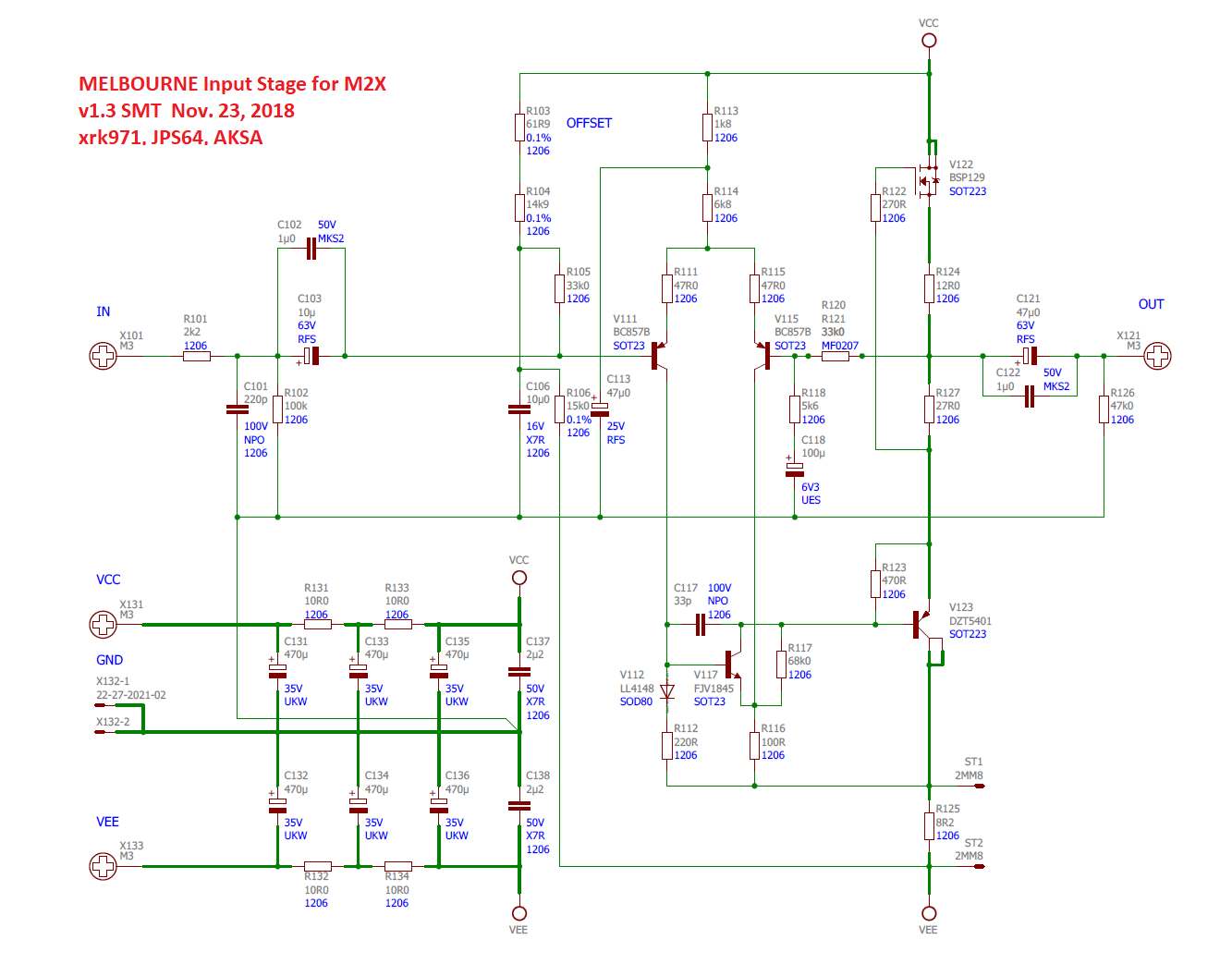
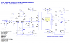
Here is latest schematic for the Melbourne DB for the M2x, which now includes a Mu-follower per Paul Bysouth's suggestion (split 39R source resistor into 12R + 27R with output at middle). CRCRC PSU now shown as well as some changes to NP caps for feedback shunt.
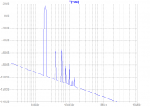
Predicted FFT for driving 4Vpp into 600ohm load (Edcor):
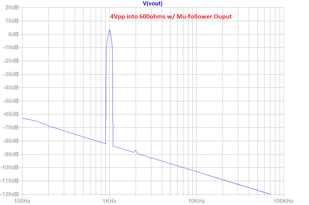
Distortion components showing THD of 0.0039%, about 3.6x improvement from previous circuit but with similar harmonic profile.
Predicted FFT for driving 4Vpp into 600ohm load (Edcor):
Distortion components showing THD of 0.0039%, about 3.6x improvement from previous circuit but with similar harmonic profile.
Code:
Harmonic	Frequency	 Fourier 	Normalized	 Phase  	Normalized
 Number 	  [Hz]   	Component	 Component	[degree]	Phase [deg]
    1   	1.000e+03	2.051e+00	1.000e+00	    0.11°	    0.00°
    2   	2.000e+03	6.065e-05	2.957e-05	  144.21°	  144.09°
    3   	3.000e+03	2.924e-05	1.426e-05	  179.98°	  179.87°
    4   	4.000e+03	2.401e-05	1.170e-05	 -179.76°	 -179.87°
    5   	5.000e+03	1.921e-05	9.365e-06	 -179.94°	 -180.05°
    6   	6.000e+03	1.600e-05	7.802e-06	 -179.95°	 -180.06°
    7   	7.000e+03	1.372e-05	6.688e-06	 -179.95°	 -180.07°
    8   	8.000e+03	1.200e-05	5.852e-06	 -179.96°	 -180.07°
    9   	9.000e+03	1.067e-05	5.202e-06	 -179.96°	 -180.08°
   10   	1.000e+04	9.602e-06	4.681e-06	 -179.97°	 -180.08°
   11   	1.100e+04	8.729e-06	4.256e-06	 -179.97°	 -180.08°
   12   	1.200e+04	8.002e-06	3.901e-06	 -179.97°	 -180.09°
   13   	1.300e+04	7.386e-06	3.601e-06	 -179.98°	 -180.09°
   14   	1.400e+04	6.859e-06	3.344e-06	 -179.98°	 -180.09°
   15   	1.500e+04	6.401e-06	3.121e-06	 -179.98°	 -180.09°
Total Harmonic Distortion: 0.003948%(0.047804%)
Last edited:
That is almost negligible distortion! I like the H3 and beyond harmonics sitting at within a bees whisker at -180 degrees. Brilliant!
Congratulations X, and Paul!
Hugh
Congratulations X, and Paul!
Hugh
Thanks, Hugh. It’s quite a nice standalone preamp even, and now can drive 600ohm loads with impunity making it useful for line driver applications.
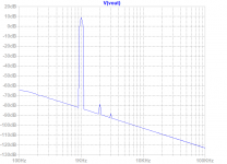
Hi X, could you use the Hann window next time you do an FFT on LTSpice so we can see a bit deeper below the bottom floor? Thanks....Predicted FFT for driving 4Vpp into 600ohm load (Edcor):...
The Melbourne daughterboards both TH and SMT have been ordered, along with an M2X main board. I will test them when I get them and build them up. In the meantime, we can go back to the integrated ALPH-M2 amp. As soon as JPS64 has some free time, he will do another layout. My simulations are showing me some limitations with this output stage, it’s not as efficient as the ALPHA’s Aleph topology - so max power will probably be closer to original 25w. To get 35w requires a huge leap in PSU voltage. Maybe some more LTSpice doodles may result in a better result. Will see...
Remember that the First Watt M2 delivers 25 watts into an 8 ohm load: (specifications on page 10 of user manual). Presumably you want your Edcor-less amplifier to deliver the same or greater power as an M2; it's just one more thing to check before sending revA PCBoards out to fab.
The Edcor transformer is quite happy to deliver beyond-the-rails signals to the MOSFET gates. Active circuits, not so much.
The Edcor transformer is quite happy to deliver beyond-the-rails signals to the MOSFET gates. Active circuits, not so much.
Last edited:
Papa Pass showed a bootstrap technique (with a couple of capacitors) as used in F4 r0 to accomplish exactly that.... The Edcor transformer is quite happy to deliver beyond-the-rails signals to the MOSFET gates. Active circuits, not so much.
Yes, bootstrapping has already been considered and tested in LTSpice. Gives more headroom for front end.
Winfield Hill, co-author of "The Art of Electronics", is a member of diyAudio. He published the schematics of his amazing power amplifier (10 MHz bandwidth, 1000 V/usec slew rate, 100 watts) here on this site:
Winfield's 100W DC-10MHz 1000V/us amplifier
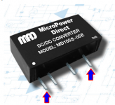
Dr. Hill used a cute trick which you might want to borrow: teeny, tiny DC_to_DC converter modules (made by MicroPowerDirect) which generate above-the-rails local power supply voltages. These local rails allow low power, upstream circuits to have bigger output swings, thereby driving large-magnitude signals into downstream circuits. The DC/DC modules are quite small: 22mm x 10mm footprint. And, more importantly, they've been tested and proven in real world amplifier applications. Admittedly this stunt was pulled off by a complete wizard, a guy who literally co-wrote THE BOOK on board-level analog design. Nevertheless, non-wizards with sufficient bravery could very likely succeed when attempting the same trick themselves.
Here is their home page: Low Cost Power Conversion Products | Micropower Direct
Winfield's 100W DC-10MHz 1000V/us amplifier
Dr. Hill used a cute trick which you might want to borrow: teeny, tiny DC_to_DC converter modules (made by MicroPowerDirect) which generate above-the-rails local power supply voltages. These local rails allow low power, upstream circuits to have bigger output swings, thereby driving large-magnitude signals into downstream circuits. The DC/DC modules are quite small: 22mm x 10mm footprint. And, more importantly, they've been tested and proven in real world amplifier applications. Admittedly this stunt was pulled off by a complete wizard, a guy who literally co-wrote THE BOOK on board-level analog design. Nevertheless, non-wizards with sufficient bravery could very likely succeed when attempting the same trick themselves.
Here is their home page: Low Cost Power Conversion Products | Micropower Direct
Hi Mark,
Actually I considered doing this from the start as JPS64 and I have designed and made many very low noise DC-DC converters built into circuits. It’s not not hard and quite effective but generally requires small SMT parts which I don’t mind. But was trying to keep an all TH design that is simple. We could run the input stage with +/-45v and have highs headroom.
Cheers,
X
... DC-DC converters built into circuits. It’s not not hard and quite effective but generally requires small SMT parts ...
???
_
Attachments
Yes, small pre-built packages exist and I have used nice ones from Murata and other companies at +/24v, but harder to find (at reasonable prices) in voltages like +/-32v which is what we need. If you have an actual part number, let me know. Rolling your own DC-DC converter for custom voltages can be done for about $10 in parts vs $50 to $70 for a COTS one.
Study the way Winfield Hill implemented it. He connects a standard 12V output DC/DC converter* in series with the existing +23V supply rail. Voila, a new +35V rail. The 12V modules are off the shelf, nothing custom. Do it again to get a new -35V rail.
It's simply a stack, like you find on a Class G switching amplifier. Bob Cordell talks about boosted rails in section 16.2, page 348. Standard stuff.
Don't forget to change the interstage coupling capacitor's voltage rating to 63V or higher. A couple dimes higher parts cost, buys infinitely greater safety.
*voltages changed to fit the modified-FirstWatt narrative here, look at Dr Hill's schematics for The Real Truth.
_
Last edited:
Hi Mark,
Thanks for the tips on adding 12v DC-DC in-series with rails. Will try that. Right now, with +/-27v main rails with bootstrapping the gates for the MOSFETs and +/-32v input stage rails I can get about 39Wrms into 8ohms (just before clip at 0.11%THD. For 1Wrms it is making 0.0042%THD mostly H2 and a bit less H3. It is a DC coupled design from front end, so no interstage coupling cap needed. Will continue to LTSpice doodle around some more...
Cheers,
X
Last edited:
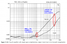
Both Douglas Self and Bob Cordell emphasize that THD @ 20kHz is a much more sensitive test of nonlinearity, as there is less "available NFB" (another way to say there is much less excess gain) at 20kHz than at 1kHz, in the high gain front end feedback circuitry. Image from Self 6th edition attached below.
_
_
Attachments
Here is V4 schematic:

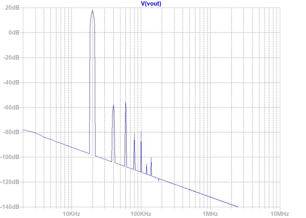
At 20kHz, the simulation predicts 0.0058% THD for 8Vpp into 8ohms (35% increase from 1kHz - so not as bad as the Class B amp you highlighted from Self's book - I guess Class A has big benefits and probably this is the "Class A smoothness" we hear).
Looks like this - not too bad:
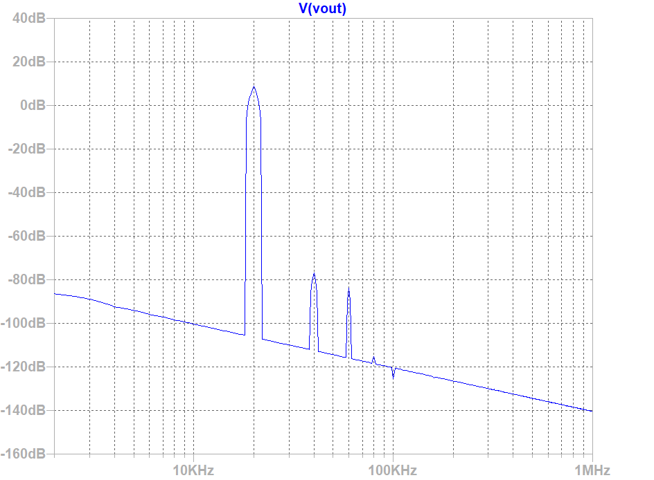
And at 22.6Vpp (8Wrms) into 8ohms, I get 0.028% THD:
Looks like this (H3 is now a bit higher than H2 - but it's a good thing I cannot hear 40kHz or 60kHz!):
So it went up a bit, but it did not go to hell in a hand-basket...
For completeness, here are sims at 1kHz
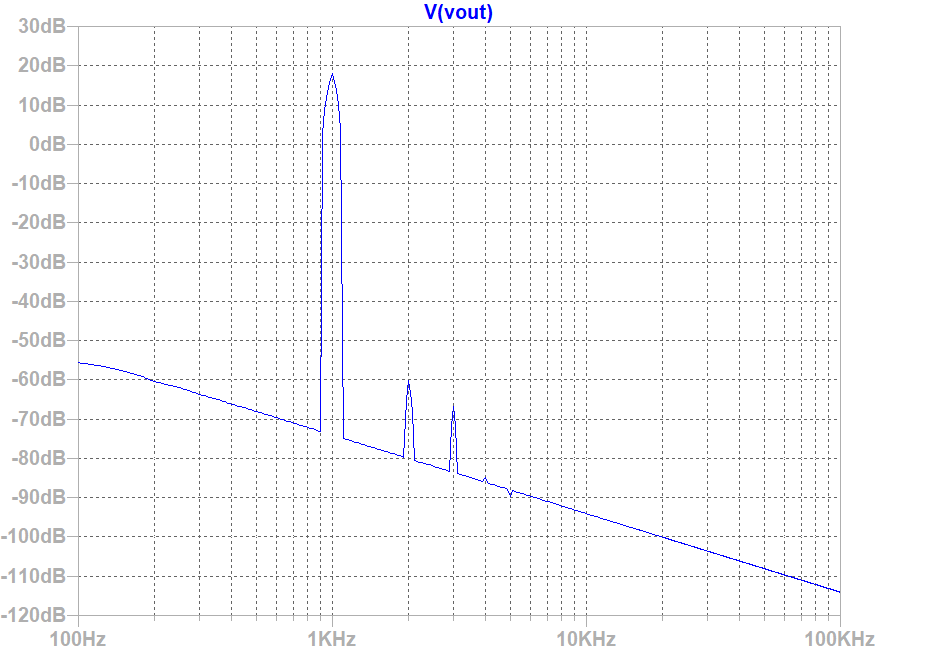
22.6Vpp into 8ohms, 1kHz excitation:
FFT looks like this:
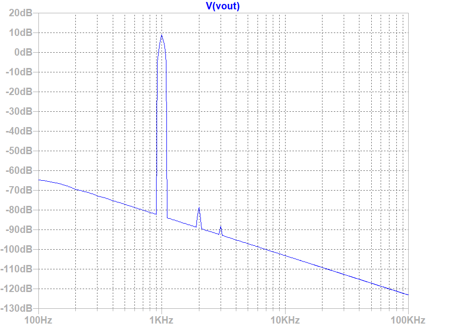
8Vpp into 8ohms at 1kHz excitation:
FFT looks like this:
At 20kHz, the simulation predicts 0.0058% THD for 8Vpp into 8ohms (35% increase from 1kHz - so not as bad as the Class B amp you highlighted from Self's book - I guess Class A has big benefits and probably this is the "Class A smoothness" we hear).
Code:
Harmonic	Frequency	 Fourier 	Normalized	 Phase  	Normalized
 Number 	  [Hz]   	Component	 Component	[degree]	Phase [deg]
    1   	2.000e+04	3.919e+00	1.000e+00	  169.14°	    0.00°
    2   	4.000e+04	2.060e-04	5.256e-05	  -95.16°	 -264.31°
    3   	6.000e+04	9.129e-05	2.330e-05	 -153.02°	 -322.16°
    4   	8.000e+04	2.411e-06	6.153e-07	  141.76°	  -27.38°
    5   	1.000e+05	7.284e-07	1.859e-07	  176.47°	    7.33°
    6   	1.200e+05	1.071e-06	2.733e-07	 -179.48°	 -348.62°
    7   	1.400e+05	9.527e-07	2.431e-07	  179.95°	   10.81°
    8   	1.600e+05	7.747e-07	1.977e-07	 -178.51°	 -347.65°
    9   	1.800e+05	7.344e-07	1.874e-07	  177.80°	    8.66°
   10   	2.000e+05	6.445e-07	1.645e-07	  179.58°	   10.43°
   11   	2.200e+05	5.970e-07	1.524e-07	  178.86°	    9.72°
   12   	2.400e+05	5.355e-07	1.366e-07	  179.54°	   10.39°
   13   	2.600e+05	5.053e-07	1.289e-07	  179.87°	   10.73°
   14   	2.800e+05	4.854e-07	1.239e-07	  179.21°	   10.07°
   15   	3.000e+05	4.405e-07	1.124e-07	 -179.98°	 -349.12°
Total Harmonic Distortion: 0.005750%(0.005995%)
Looks like this - not too bad:
And at 22.6Vpp (8Wrms) into 8ohms, I get 0.028% THD:
Code:
Harmonic	Frequency	 Fourier 	Normalized	 Phase  	Normalized
 Number 	  [Hz]   	Component	 Component	[degree]	Phase [deg]
    1   	2.000e+04	1.112e+01	1.000e+00	  169.13°	    0.00°
    2   	4.000e+04	1.848e-03	1.662e-04	  -90.42°	 -259.55°
    3   	6.000e+04	2.472e-03	2.224e-04	 -151.58°	 -320.71°
    4   	8.000e+04	1.224e-04	1.101e-05	  104.10°	  -65.03°
    5   	1.000e+05	1.550e-04	1.394e-05	    3.75°	 -165.38°
    6   	1.200e+05	7.696e-06	6.922e-07	 -113.44°	 -282.57°
    7   	1.400e+05	1.357e-05	1.220e-06	  160.15°	   -8.98°
    8   	1.600e+05	2.004e-06	1.802e-07	  166.89°	   -2.24°
    9   	1.800e+05	1.540e-06	1.385e-07	 -156.18°	 -325.31°
   10   	2.000e+05	1.779e-06	1.600e-07	 -179.06°	 -348.19°
   11   	2.200e+05	1.579e-06	1.420e-07	  178.17°	    9.04°
   12   	2.400e+05	1.417e-06	1.274e-07	 -179.99°	 -349.12°
   13   	2.600e+05	1.326e-06	1.193e-07	  179.87°	   10.74°
   14   	2.800e+05	1.229e-06	1.106e-07	 -179.87°	 -349.00°
   15   	3.000e+05	1.149e-06	1.033e-07	 -179.95°	 -349.08°
Total Harmonic Distortion: 0.027817%(0.027861%)
Looks like this (H3 is now a bit higher than H2 - but it's a good thing I cannot hear 40kHz or 60kHz!):
So it went up a bit, but it did not go to hell in a hand-basket...
For completeness, here are sims at 1kHz
22.6Vpp into 8ohms, 1kHz excitation:
Code:
Harmonic	Frequency	 Fourier 	Normalized	 Phase  	Normalized
 Number 	  [Hz]   	Component	 Component	[degree]	Phase [deg]
    1   	1.000e+03	1.126e+01	1.000e+00	  179.13°	    0.00°
    2   	2.000e+03	1.392e-03	1.236e-04	  -92.96°	 -272.10°
    3   	3.000e+03	5.980e-04	5.309e-05	 -169.21°	 -348.34°
    4   	4.000e+03	5.303e-05	4.709e-06	  139.25°	  -39.89°
    5   	5.000e+03	2.055e-05	1.825e-06	  152.80°	  -26.34°
    6   	6.000e+03	2.362e-05	2.097e-06	 -177.33°	 -356.46°
    7   	7.000e+03	2.091e-05	1.857e-06	 -176.98°	 -356.12°
    8   	8.000e+03	1.801e-05	1.599e-06	 -179.55°	 -358.69°
    9   	9.000e+03	1.596e-05	1.417e-06	 -179.82°	 -358.96°
   10   	1.000e+04	1.438e-05	1.277e-06	 -179.58°	 -358.71°
   11   	1.100e+04	1.308e-05	1.161e-06	 -179.59°	 -358.73°
   12   	1.200e+04	1.199e-05	1.064e-06	 -179.66°	 -358.79°
   13   	1.300e+04	1.107e-05	9.825e-07	 -179.68°	 -358.82°
   14   	1.400e+04	1.028e-05	9.123e-07	 -179.71°	 -358.84°
   15   	1.500e+04	9.591e-06	8.515e-07	 -179.72°	 -358.86°
Total Harmonic Distortion: 0.013471%(0.018055%)
FFT looks like this:
8Vpp into 8ohms at 1kHz excitation:
Code:
Harmonic	Frequency	 Fourier 	Normalized	 Phase  	Normalized
 Number 	  [Hz]   	Component	 Component	[degree]	Phase [deg]
    1   	1.000e+03	3.970e+00	1.000e+00	  179.14°	    0.00°
    2   	2.000e+03	1.610e-04	4.055e-05	  -99.31°	 -278.45°
    3   	3.000e+03	3.884e-05	9.785e-06	 -173.69°	 -352.83°
    4   	4.000e+03	1.263e-05	3.182e-06	  178.84°	   -0.29°
    5   	5.000e+03	1.002e-05	2.524e-06	 -179.37°	 -358.50°
    6   	6.000e+03	8.389e-06	2.113e-06	 -179.29°	 -358.43°
    7   	7.000e+03	7.191e-06	1.811e-06	 -179.40°	 -358.54°
    8   	8.000e+03	6.292e-06	1.585e-06	 -179.48°	 -358.61°
    9   	9.000e+03	5.593e-06	1.409e-06	 -179.54°	 -358.67°
   10   	1.000e+04	5.034e-06	1.268e-06	 -179.59°	 -358.72°
   11   	1.100e+04	4.576e-06	1.153e-06	 -179.62°	 -358.76°
   12   	1.200e+04	4.195e-06	1.057e-06	 -179.66°	 -358.79°
   13   	1.300e+04	3.872e-06	9.754e-07	 -179.68°	 -358.82°
   14   	1.400e+04	3.596e-06	9.057e-07	 -179.69°	 -358.83°
   15   	1.500e+04	3.356e-06	8.453e-07	 -179.72°	 -358.86°
Total Harmonic Distortion: 0.004214%(0.012661%)
FFT looks like this:
Attachments


Last edited:
NMOS source resistor R24 is 3 times greater than PMOS source resistor R25. Does that mean you want new reference voltage ICs in positions U2 and U3? Perhaps in your schematic with unequal resistors, one of U2/U3 needs to have a "zener breakdown" voltage which is 3x the other? Right now they are both 1.2 volts.
BTW there is a schematic hookup glitch at the cathode of D2. May not be anything important but there is a wayward solder dot.
BTW there is a schematic hookup glitch at the cathode of D2. May not be anything important but there is a wayward solder dot.
Hi Mark,
I was adding asymmetry to increase H2 relative to H3 since the bootstrapping seemed to alter the harmonic profile to H3 dominant. Despite not changing the 1.2v voltage reference ICs there, it still seems to work in LTSpice. I will check that extra joint dot on K of D2.
Thanks for checking so carefully. You have good eyes.
THe 32v rails can be had with a simple voltage doubler and regulator from the main 27v transformer.
X, not everyone is going to be able to reliably maintain continuous ~75W dissipation on TO247 Mosfets. Potential builders should be provided with reccomendations of required heat management in sufficient detail and I would think that some type of overheat protection is mandatory.
- Status
- Not open for further replies.
- Home
- Amplifiers
- Solid State
- AKSA Lender Pass Hybrid M2 (ALPH-M2) Amp