It actually might have.I don't know that DAC, but presumably it either has a lower output signal level than 2 V RMS, or it has some kind of DC-DC converter on board. For example, a charge pump converter to generate -5 V from the +5 V rail could do the trick.
See this sentence from a review about it:
Taken from here:Since the Modi 3 has a dedicated power-input using a micro USB termination, it is possible to use power supplies other than the SMPS USB wall-wart that Schiit includes.
In doing so, bear in mind that the Modi 3 has an internal SMPS as the first thing encountered after the power-input,
so using an expensive external linear power supply is still going to result in power going through a switcher.
In listening tests, I could discern no difference at all between a simple direct USB connection, a powered USB hub, the Schiit supplied wall-wart, an iFi iPower 5v or my high-end linear lab-supply.
Schiit Audio Modi 3 - Desktop DAC - Review - headphone.com
BTW, here's a good picture of the PCB:
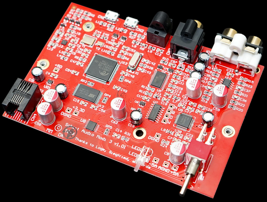
We can see 2 tiny 6-leg chips right near the second Micro-USB socket,
altho from this image we cannot see what printed on these chips.
Last edited:
Yes. Thanks for correcting me. Blame it on my age!MarcelvdG said:I think you mean 5.657 V peak-peak
From what I heard from people, such DACs are for example:
- TDA1541A S1 and S2
and
- AD1862 (which is 20bit)
Is it possible to get them today, somehow?
I built this one:
AD1862 R2R Isolated nonoversampling NOS Audio DAC with FIFO reclock - DIYINHK
Sounds good, not sure how good the implementation is specifically.
Next up tubizator i/v for it.
I built this one:
AD1862 R2R Isolated nonoversampling NOS Audio DAC with FIFO reclock - DIYINHK
Sounds good, not sure how good the implementation is specifically.
Next up tubizator i/v for it.
The pcb seems fine but I cannot identify the chips labelled DRC1 and DRC3.
I've bought a couple of them and have almost finished connecting one up.
Did you receive the correct capacitors for the NR pins - 1 & 10uf respectively and of Tantalum, not aluminium electroytic. They sent me only 150uf and 1uf decoupling caps.
They also failed to print on the board that the I2S input is 3.3v and not 5v.
Also, they are misleading buyers a little by claiming 'stopped clock' without explaining what this means. In fact, only the clock to the left dac is stopped whilst the data is clocked into the right dac. (this is explained in AD's application note).
I am using I/V transformers rather than opamp or tubes.
I have a SRC4192 sample rate converter on order so I can input any bit depth and sample rate and output 20bit for the AD1820.
This looks like another important parameter of a DAC, that affects the sound.I am using I/V transformers rather than opamp or tubes.
Altho this specific choice - an I/V transformers, was not mentioned a lot as the preferred one.
Mostly tubes are the preferred option.
Hopefully I would have the chance to hear the difference between all 3 options, sometime.
This looks like another important parameter of a DAC, that affects the sound.
Altho this specific choice - an I/V transformers, was not mentioned a lot as the preferred one.
Mostly tubes are the preferred option.
Hopefully I would have the chance to hear the difference between all 3 options, sometime.
Transformers do have a sound of their own, but on the other hand they are much simpler to use. There is no need for high voltages, additional mains supplies and of course tubes also have a sound of their own. (although to be preferred over semiconductors)
But the main reason they are not popular is the cost, in my opinion and that's why they tend to found only in very high end dacs.
I have a SRC4192 sample rate converter on order so I can input any bit depth and sample rate and output 20bit for the AD1820.
Just a free advice: when you use asynchronous sample rate conversion, choose an unusual output sample rate, such that sum and difference frequencies of the input and output bit clocks and their harmonics are outside the audible range.
BTW,
again regarding the interesting thing that MarcelvdG wrote:
I wrote earlier that in some review, the reviewer wrote:
something that was said by 1 of the 2 owners of the Schiit company:
(who are also the designers of the circuit)
So from 5v they create a Dual Rail power..
Definitely seems that they know what they're doing.
That's what made me buy it today.
again regarding the interesting thing that MarcelvdG wrote:
I don't know that DAC, but presumably it either has a lower output signal level than 2V RMS,
or it has some kind of DC-DC converter on board. For example, a charge pump converter to generate -5 V from the +5 V rail could do the trick.
I wrote earlier that in some review, the reviewer wrote:
So in another (second) review, I found a bit more information about it,bear in mind that the Modi 3 has an internal SMPS as the first thing encountered after the power-input,
so using an expensive external linear power supply is still going to result in power going through a switcher.
something that was said by 1 of the 2 owners of the Schiit company:
(who are also the designers of the circuit)
The New Schiit Modi 3, $99 PriceNow, Modi 3 gives you ... a dual rail power supply and full 2.0v RMS output
So from 5v they create a Dual Rail power..
Definitely seems that they know what they're doing.
That's what made me buy it today.
Just a free advice: when you use asynchronous sample rate conversion, choose an unusual output sample rate, such that sum and difference frequencies of the input and output bit clocks and their harmonics are outside the audible range.
Thanks for the advice.
Actually, in my experience, the most transparent I/V stages have been based on opamps. Either following a low value resistor used as passive I/V or directly (but with an extra buffer in the loop). Exotic solutions as tubes and transformers sound nice but not as "open" to me.
You will quickly realized that some parameters are the subjects of opinions rather than settled consensus.
You will quickly realized that some parameters are the subjects of opinions rather than settled consensus.
In some DAC products, they like to specify also the opamp they used, not just the DAC chip..Actually, in my experience, the most transparent I/V stages have been based on opamps.
Example:

In some cases they even put the opamp in a chip socket,
so the user can replace it, if he has some personal preference toward some other opamp.
Are there ones that are known to be more transparent?
And other that are to be avoided?
Last edited:
Technically the main problem is keeping the op-amp out of slewing at all times, so op-amps with high slew rates and with high ratios of slew rate to gain-bandwidth product should work well. (The ratio of the slew rate to the gain-bandwidth product is proportional to the error voltage the op-amp can handle without slewing.)
A low open-loop output impedance could also help, because it reduces the voltage step you get at the op-amp's input when the DAC switches (assuming there is a capacitor between the output and the input of the op-amp, as there usually is).
A low open-loop output impedance could also help, because it reduces the voltage step you get at the op-amp's input when the DAC switches (assuming there is a capacitor between the output and the input of the op-amp, as there usually is).
ESS recommends opamps based on distortion measurements they have taken. Of course their dacs are capable of very low distortion, but only if the implementation is good enough. They have advice on their website downloads page.
With cheap imported dacs, it looks like the designers find they can sell more if the opamps are socketed. They know some people like opamp rolling to find a sound they like. Usually, the implementations of those dacs aren't very good, so going for opamps that end up producing the least distortion at that output is probably futile.
With cheap imported dacs, it looks like the designers find they can sell more if the opamps are socketed. They know some people like opamp rolling to find a sound they like. Usually, the implementations of those dacs aren't very good, so going for opamps that end up producing the least distortion at that output is probably futile.
This looks like another important parameter of a DAC, that affects the sound.
Altho this specific choice - an I/V transformers, was not mentioned a lot as the preferred one.
Another issue which in my experience can make a highly significant difference to the SQ is the presence of passive filtering between the DAC and the following active circuitry. Whilst its commonly used terminology to call a transformer after a DAC 'an I/V transformer' I/V conversion isn't what its doing. Rather its isolating and filtering the 'raw' DAC output prior to it hitting downstream stages.
Whilst its commonly used terminology to call a transformer after a DAC 'an I/V transformer' I/V conversion isn't what its doing.
Agreed. Usually there is a low value resistor from dac output to ground that does the I/V conversion. The transformer primary bridges the resistor and couples the signal (voltage across the resistor) to subsequent voltage amplification stages.
Usually there is a low value resistor from dac output to ground that does the I/V conversion. The transformer primary bridges the resistor and couples the signal (voltage across the resistor) to subsequent voltage amplification stages.
Yes, that's my understanding too of how transformers are normally used, in voltage mode in conjunction with a resistor for I/V. There is another way to use a transformer though, one I'm currently (pun intended) exploring. That's using the transformer to couple the current (rather than the voltage) to the subsequent I/V stage on the secondary (rather than the primary).
- Status
- This old topic is closed. If you want to reopen this topic, contact a moderator using the "Report Post" button.
- Home
- Source & Line
- Digital Line Level
- Important Parameters When Choosing a DAC