I apologize but I forgot to mention that the zener was tested out of the circuit. What I had read about that was it should read high resistance in one direction, and lower in the other. It didn't. It ready 40ohms in both directions. I tried the test on some zener that I had laying about and they followed the quoted pattern. 57meg ohm vs 26meg ohms. Hence my conclusion that the zener is faulty.
The caps are wired properly but I will check again.
If the Zener reads low resistance (40 ohms) out of circuit then it is faulty.
We now have to look at how that could occur and we see that the Zener is connected via a 10k to the negative rail. That resistance places an absolute limit on the current that can flow and for a -/+30 volt (so 60 volts in total) we can not get more than 6 milliamps flowing which in turn would give a total power dissipation in the Zener of around 100 milliwatts. That's worst case.
The cap is the only other non defined pathway and could if reverse biased or faulty allow higher current to flow (but you would need a faulty chip and a faulty cap to do that, not just one or the other)
- Item Bad Good
- R5 0 12.15 !
- Z1 15.4 16
- R6 0 0
- R8 0 0
- C11 31 31
- C12 -31 -31
- C6 -31 0 !
- V- -31 -31
- V+ 31 31
- Pins
- 1 31+ 31+
- 2 0 0
- 3 -31 0
- 4 -31 -31
- 5 0 31
- 6 0 0
- 7 0 0
- 8 -16 -3.3
- 9 -15 0
- 10 -15 0
- 11 0 0
Well I took voltage readings from the working and non working and there are the results. I apologize for the format as I have no clue as to how to format to make it readable.
In the process of trying to figure out why R5 had a 12 volt drop on the working amp, and 0 on the bad one I tried to remove C6 so I could read it's capacitance. In the process I pulled the connector out of C6 so I am ordering 2 more of them
In the meantime, here are the readings so if you see anything glaring, please let me know.
Just for now I am going to use one of my capacitors to see if that was it.
Did I say that I am getting sick of this beast.

Thanks a lot for your help
- Item Bad Good
- R5 0 12.15 !
That's either a problem or a measurement error. 0 V across R5 means the chip is muted. In that case the output voltage should be 0 V (or the same as on pin 7).
- C6 -31 0 !
That's caused by the output voltage being -31 V on the bad channel. C6 is most likely fine.
- Pins
- 1 31+ 31+
- 2 0 0
- 3 -31 0
- 4 -31 -31
- 5 0 31
Pin 1 and pin 5 should both connect to VCC, thus, should both read +31 V. If you connect pin 5 to VCC, the amp might start to work.
Tom
Thank you Mark.Measure or just replace R3 and C4. Also check that there is a good connection between input gnd and power gnd.
I removed C4 to check at 2 different testers. One yielded 498.4uf Esr= .24ohm
#2 measured 499 I think.
R3 measured .96k
Solid connection btwn input and and power gnd.
Something caused some changes.
R5 is now 13.36
Pins:
5 31
It might have been that originally and I misread it.
I am going to torque the board and see if it seems faulty. Pretty soon I am going to start removing parts and solder a new board. Dang but that is not fun.
ps ive built this and it sounds fantastic just make sure to measure and test parts before the board installation and soldering i made sure a heat sink was attached to chip before i soldered and waited at least a till it cooled before soldering another pin.and used thermal grease and a good sill pad .from your pic everything looks correct .good luck also measure your transformer .i also used a bulb suppressor for initial start up
you also forgot the feedback resistor 20k from pins 3 to 9
No, it's there.
ps ive built this and it sounds fantastic just make sure to measure and test parts before the board installation and soldering i made sure a heat sink was attached to chip before i soldered and waited at least a till it cooled before soldering another pin.and used thermal grease and a good sill pad .from your pic everything looks correct .good luck also measure your transformer .i also used a bulb suppressor for initial start up
Thank you Kallel, for your words of encouragement. I am pretty much convinced that this board is a loss and will begin disassembly tomorrow. Gad but I don't look forward to that.
I am going to torque the board and see if it seems faulty. Pretty soon I am going to start removing parts and solder a new board. Dang but that is not fun.
Stay focused! Pin 5 should be connected to the +31. It's pretty much nonsensical to start measuring all kinds of parts before you make sure the unit is wired up correctly in the first place!
Why start a new board, with probably same/similar/other errors again? Do you really want to fix this or do you enjoy this kind of discussion??
Jan
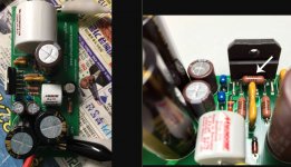
I have also built an amp using this board. It does work. Could you provide a picture of the board (how it is currently wired).
He did all the measurements. Clearly his wiring is faulty - for instance, one power supply wiring is missing.
Yet apparently he can't get himself to fix it and methodologically fix the others one after another.
I'm out of here, good luck.
Jan
Jan, I will do whatever is suggested. I think that folks are running out of ideas. Pin 5 did measure +35.Stay focused! Pin 5 should be connected to the +31. It's pretty much nonsensical to start measuring all kinds of parts before you make sure the unit is wired up correctly in the first place!
Why start a new board, with probably same/similar/other errors again? Do you really want to fix this or do you enjoy this kind of discussion??
Jan
The LM3886 on this board has been replaced as the previous one went up in smoke.
Do you have a suggestion as to what to look for ?
He did all the measurements. Clearly his wiring is faulty - for instance, one power supply wiring is missing.
Yet apparently he can't get himself to fix it and methodologically fix the others one after another.
I'm out of here, good luck.
Jan
Not clearly and the power supply wire is not missing. I have the exact same board working properly as part of a 2-board set.
I was trying to use this problem as a learning tool to try and teach myself how to go about troubleshooting a problem of this nature.
So, instead of getting all snippy, teach me how to go about diagnosing this type of problem. I have tried all the suggestion and I am still stuck.
By the way, I'm not seeing your 20k feedback resistor R4 between pin 3 and 9 on your photo in post 1.
It's there.

What are your measurements now that you replaced the chip?
Pin 3 ok now or full negative rail?
What are you getting from GND to Pin 8 and each side of R5?
In the process of removing the LM3886 I saw that 1 pin was folded under rather than thru the hole. Well I straightened it out and pushed it back in. So I am still using the prior albeit it's beginning to look a little abused. On to the reading.
R5 -2.814 -31, voltage drop of 28.9.
P3 -1.9
And the other readings that have changed.
C6 -1.6
P3 -1.9
P4 -1.9
P8 -2.7
P9 -1,8
P10 -1.8
Please ignore the missing C6 as it is mounted on the backside.
I am tempted to remove LM3886 and clean it up.
The reading of -1,9 at the output is encouraging. We're getting closer.
Thanks
Last edited:
- Status
- This old topic is closed. If you want to reopen this topic, contact a moderator using the "Report Post" button.
- Home
- Amplifiers
- Chip Amps
- Different amp same trouble. Lm3886 can't get working