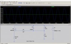
I've been trying to sim a simple cap-multiplier circuit. It's a somewhat inaccurate model (my source is just a sine wave over dc), but that part works as expected.
However, if I output data from time=0, I don't get the slow rise I think I should. Shouldn't there be an initial current surge over R2 (and a corresponding slow voltage rise on the node between them) until C1 is charged? All I get is a constant sine-wave from the AC.
What is it that I'm doing wrong?
Thanks,
Jeff.
Attachments
Shouldn't there be an initial current surge over R2 (and a corresponding slow
voltage rise on the node between them) until C1 is charged?
Right. Is your measured voltage defined as DC or AC coupled?
I'm plotting "V(n001)". Does that give me an AC-coupled value? How do I specify DC?
Examples:
Plot the DC voltage between nodes 1 and 2,
the voltage at node 3,
and the current through the voltage source, Vmeas
.PLOT DC V(1,2) V(3) I(Vmeas)
https://web.stanford.edu/class/ee133/handouts/general/spice_ref.pdf
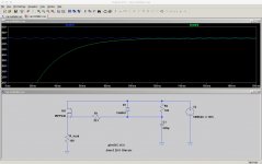
You may need to use a PWL transient source for the DC part starting at t=0,
in series with an AC transient source also starting at t=0.
Last edited:
What is it that I'm doing wrong?
Thanks,
Jeff.
You are assuming that everything starts at zero. Unless explicitly instructed to do otherwise, LTSpice or any other simulator I know of first calculates a DC bias point and takes it from there. For stable circuits this is the response you would have got if the values you apply at t = 0 had been there from t = -infinity onwards.
- Status
- Not open for further replies.