Hi guys!
I need your support!")
I'm building two amp boards based on the old TCA940 (10 watt per channel).
I'm searching for a power transformer (I hope I'm using the right technical words!)
In order to get the best performance from this old chips (even I know they're not Hi-Fi ICs), I'll search for a 20 V power transformer using very big heat sinks for the two TCA940...but I don't know how many watt (or VA, is this word right?) and ampere the power transformer must have, to get the best sound results from these two amp boards.
So, please guys, could you give me advice about that?
This is the link with the TCA940 technical features:
TCA940 pdf, TCA940 description, TCA940 datasheets, TCA940 view ::: ALLDATASHEET :::
Thank you in advance for your patience and kindness.
Best regards
I need your support!
I'm building two amp boards based on the old TCA940 (10 watt per channel).
I'm searching for a power transformer (I hope I'm using the right technical words!
)In order to get the best performance from this old chips (even I know they're not Hi-Fi ICs), I'll search for a 20 V power transformer using very big heat sinks for the two TCA940...but I don't know how many watt (or VA, is this word right?) and ampere the power transformer must have, to get the best sound results from these two amp boards.
So, please guys, could you give me advice about that?
This is the link with the TCA940 technical features:
TCA940 pdf, TCA940 description, TCA940 datasheets, TCA940 view ::: ALLDATASHEET :::
Thank you in advance for your patience and kindness.
Best regards
If you give me a concrete watt value for the power transformer, you would make me happy.
The circuit needs need 2 x 10W plus 10% for losses at a minimum, or 22VA.
Then go at least 50% more, so around 35VA or 50VA.
For a 24VDC supply, you need a 18VAC-0-18VAC secondary (or two 18VAC in series
to form a center tap).
So you need a 35VA or 50VA transformer with 2 x 18VAC secondaries.
Last edited:
Thank you very much Rayma!
A small toroid type transformer should be fine.
...need 2 x 10W plus 10% for losses.... Then go at least 50% more...
Hmmmmm.... assuming class B, 78% efficient in theory but 60% in practice especially for older smaller chips. So 20W out needs 20W*(1/0.6) or 33 Watts of DC.
The AC-to-DC conversion is hard in a transformer. For really solid no-sag test-bench power we might go 2X the DC W to get AC VA. For "it works!" clean music we can skimp to 1.5X. 66VA to 50VA. 20VAC with 3.3 to 2.5 Amps AC.
We agree the 50VA is fine. I believe the 35VA solution will be "saggy". However I concede that many "popular price stereos" probably used 35VA here....
Hey PRR, thank you so much for your help!
Guys, by the way, I've an old Grundig "all in one system" (Dual turntable + 2x8 watt RMS stereo amplifier) for spare parts.
It's the Grundig Studio 80:
Grundig Studio 80
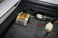
I've checked with a multimeter the transformer secondary output: 18,5 volt (see the picture, it's not a symmetrical power supply as the red and black cable confirms!)
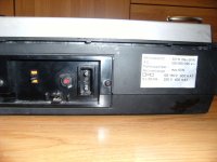
55 watt max comsuption (the back label says) minus 10 watt of Dual turnatble, it would be 45 watt.
Do you think I can use this transformer? or maybe is it better to buy a new one with better specs?
Please take a look at the pictures: you can see the transformer in question, please tell me what do you think about it
Thank you once again for your precious support!
Regards
Guys, by the way, I've an old Grundig "all in one system" (Dual turntable + 2x8 watt RMS stereo amplifier) for spare parts.
It's the Grundig Studio 80:
Grundig Studio 80
I've checked with a multimeter the transformer secondary output: 18,5 volt (see the picture, it's not a symmetrical power supply as the red and black cable confirms!)
55 watt max comsuption (the back label says) minus 10 watt of Dual turnatble, it would be 45 watt.
Do you think I can use this transformer? or maybe is it better to buy a new one with better specs?
Please take a look at the pictures: you can see the transformer in question, please tell me what do you think about it
Thank you once again for your precious support!
Regards
Attachments
Last edited:
hey guys, please what do you think about the transformer and its specs?
Could I use it or Have I buy a new one?
Seems like it would work, give it a shot. If there is only one
secondary winding, then use a FWB rectifier circuit.
http://www.circuitstoday.com/wp-content/uploads/2009/08/bridge_rectifier_with_capacitor_filter.jpg
The circuit needs need 2 x 10W plus 10% for losses at a minimum, or 22VA.
Then go at least 50% more, so around 35VA or 50VA.
For a 24VDC supply, you need a 18VAC-0-18VAC secondary (or two 18VAC in series
to form a center tap).
So you need a 35VA or 50VA transformer with 2 x 18VAC secondaries.
I usually use 50% more too. Seems to have worked well for me for 40 years !
Hi Rayma, you can imagine how you're helping me...so thank you so much
As I say always I'm just a newbie, so if I say wrong things, please have mercy on me!
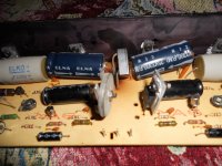
I was thinking one thing, maybe a silly thing: this transformer was feeding, when my "Grundig stereo center" was a "working device", an amp board with 4 audio Integrated Circuits (as you can see in the picture below of the original Grundig amp board): 2 audio Integrated Circuits for each channel, of course.
So my theory (please tell me if I'm wrong) is: if this transformer can feed 4 ICs (moreover hi-fi quality ICs as the "BD serie"...it should not have problems to feed just two "no hi-fi quality" ICs like the two TCA940, that are a sort of "toy-stuff".
I repeat guys, my theory could be absolutely wrong and incorrect, only you can say that.
Just a last think, Rayma, please could you explain (briefly, if you want) what does mean "FWB rectfier circuit"?...I only know what is a normal "recfier bridge circuit" but not a FWB one.
Thank you for supporting me, my friends
I know that it requires a lot of patience
Regards.
As I say always I'm just a newbie, so if I say wrong things, please have mercy on me!
I was thinking one thing, maybe a silly thing: this transformer was feeding, when my "Grundig stereo center" was a "working device", an amp board with 4 audio Integrated Circuits (as you can see in the picture below of the original Grundig amp board): 2 audio Integrated Circuits for each channel, of course.
So my theory (please tell me if I'm wrong) is: if this transformer can feed 4 ICs (moreover hi-fi quality ICs as the "BD serie"...it should not have problems to feed just two "no hi-fi quality" ICs like the two TCA940, that are a sort of "toy-stuff".
I repeat guys, my theory could be absolutely wrong and incorrect, only you can say that.
Just a last think, Rayma, please could you explain (briefly, if you want) what does mean "FWB rectfier circuit"?...I only know what is a normal "recfier bridge circuit" but not a FWB one.
Thank you for supporting me, my friends
I know that it requires a lot of patience
Regards.
Attachments
if this transformer can feed 4 ICs (moreover hi-fi quality ICs as the "BD serie"...
it should not have problems to feed just two "no hi-fi quality" ICs
what does mean "FWB rectfier circuit"?
There are some details, but your thinking (for the VA rating) is reasonable.
Circuits can require different voltages though, and would then need different transformers.
If you have only one secondary winding (or two identical windings in parallel)
you would use a Full Wave Bridge rectifier circuit, which is connected like this.
http://www.circuitstoday.com/wp-content/uploads/2009/08/bridge_rectifier_with_capacitor_filter.jpg
If you have two identical windings in series, or one winding with a center tap,
you would use a Full Wave Center Tapped rectifier circuit, like this.
https://www.electronics-notes.com/images/diode-full-wave-rectifier-centre-tapped-transformer-01.svg
Does your power transformer have multiple output terminals, or just two?
Sometimes there are three output terminals, the odd one is the center tap.
Last edited:
thank you, teacher Rayma
If you see the picture with the transformer, you'll notice that the secondary output only have two pins with a black-red cable connected to...in other side of the transformer, there're several pins as you can see, but they're for the cables of the voltage selector on the back
Thank you...your help is like gold.
Regards
the secondary output only have two pins with a black-red cable connected
Ok, then use either four 100V 3A diodes, or a single 100V diode block,
whichever you prefer. Usually those blocks are rated at 35A. Some examples:
https://www.vishay.com/docs/88516/1n5400.pdf
HVCA - KBPC3501 - Bridge Rectifier; 100V; 400A; 70V; 35A - Allied Electronics & Automation
Last edited:
Ok, then use either four 100V 3A diodes, or a single 100V diode block,
whichever you prefer. Usually those blocks are rated at 35A. Some examples:
https://www.vishay.com/docs/88516/1n5400.pdf
HVCA - KBPC3501 - Bridge Rectifier; 100V; 400A; 70V; 35A - Allied Electronics & Automation
Very wel, maestro!
Now I'll buy the TCA940 PCB, I'll mount them and then I'll build all the power supply section!
I now that with your supervision there will be no problems!

ciao!

The circuit needs need 2 x 10W plus 10% for losses at a minimum, or 22VA.
Then go at least 50% more, so around 35VA or 50VA.
For a 24VDC supply, you need a 18VAC-0-18VAC secondary (or two 18VAC in series
to form a center tap).
So you need a 35VA or 50VA transformer with 2 x 18VAC secondaries.
Dear Rayma, I've a question, I hope you can help me: does a trasformer with a secondary output of 18 volt (no-symmetrical, there're just two pins) after the rectifier circuit produce 24 volt as you said?
Apologize for my ignorance...it's vey probably I'm wrong, but isn't the real voltage of 18 volt, after the rectifier circuit, 22 volt ?
Please, Rayma, be patience...and if you can correct me, if I'm wrong
Thank you so much for your precious help!
Regards from Italy
Single secondary 0-18vac will give approximately 24vdc after rectification:
18*1.414 = 25.452.
Subtract 2 diode drops for the rectifier at about 0.7 each:
25.452 - 1.4 = 24v.
That will only give you a single +24v rail (you can't get +24/-24).
Only rough calculation, there may be other voltage losses but a good enough guide.
18*1.414 = 25.452.
Subtract 2 diode drops for the rectifier at about 0.7 each:
25.452 - 1.4 = 24v.
That will only give you a single +24v rail (you can't get +24/-24).
Only rough calculation, there may be other voltage losses but a good enough guide.
Thank you Avtech23!
Honestly I don't understand what it does mean" That will only give you a single +24v rail (you can't get +24/-24)"
I was referring to the total power output of the secondary...not to a single rail...Sorry...I'm a newbie and so ignorant in electronics!
Anyway thank you so much
Honestly I don't understand what it does mean" That will only give you a single +24v rail (you can't get +24/-24)"
I was referring to the total power output of the secondary...not to a single rail...Sorry...I'm a newbie and so ignorant in electronics!
Anyway thank you so much
The TCA940 is a single rail power amp with an absolute maximum supply rating of 25 volts, with 18 volts being a more reasonable figure for reliability. That means you need a transformer of 12 to 15 volts AC.
You wont get more than about 4 to 5 watts rms into 8 ohms from one of these, and you also need a suitable heatsink which is easier said than done.
You wont get more than about 4 to 5 watts rms into 8 ohms from one of these, and you also need a suitable heatsink which is easier said than done.
- Status
- This old topic is closed. If you want to reopen this topic, contact a moderator using the "Report Post" button.
- Home
- Amplifiers
- Power Supplies
- How many watt (from the power tranfromer) to feed two old TCA940 amp boards