What's the best single point to connect the signal ground to chassis ground: input RCA signal ground or 1st capacitors mains PSU?
What's the best grounding: mains GND & signal ground togheter at a single point of chassis or separate with two points, one for AC safety ground & the other for signal GND?
What's the best grounding: mains GND & signal ground togheter at a single point of chassis or separate with two points, one for AC safety ground & the other for signal GND?
I connect signal ground to chassis ground at the RCA jacks. I connect the AC safety ground at the chassis, by itself, about 2 inches from the IEC connector.
In my case, the entire aluminum chassis is ground. I just tie the RCA to ground at the jack, and the House AC beside the power jack.
AC safety ground must have its own connection to the chassis as required by law. There are literally thousands of posts on this very same topic, suggest that you do a search and read them.
Yes there is a lot of information but I'm not sure what's the correct way to do it, so why ask here.
Last edited:
Signal ground and chassis safety ground should be separate. Connection between the two only with diodes/capacitor in between. See this for information: http://hifisonix.com/wordpress/wp-content/uploads/2018/07/How-to-wire-up-an-amplifier_3.pdf
Although it is written with solid state in mind, the principles apply to tubes too.
Although it is written with solid state in mind, the principles apply to tubes too.
Thanks Ben, your linked paper said: "The signal return is bonded to the chassis through a single connection from the power supply 0V to the metal chassis" Rob from DHTRob does attached pic and I read for example Elliot Sound that shares the same chassis point signal GND & signal GND trought a SLB attached pic so still confused what's the proper way.
Attachments
Last edited:
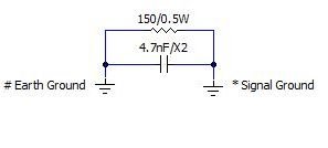
I believe that the connection to chassis ground should be through bridge/capacitor as shown in the second picture. The article that I referenced also shows that.
Here Rod Elliot earthing the mains PSU to chassis.
ValveWizard uses separate points to signal GND and safety mains AC earth, also says to take the input RCA signal ground to chassis in place of 1st cap mains AC filter PSU indicated in other places.
http://www.valvewizard.co.uk/Grounding.pdf
It's really so complicate to know what's the correct way, I'm puzzled.
An externally hosted image should be here but it was not working when we last tested it.
ValveWizard uses separate points to signal GND and safety mains AC earth, also says to take the input RCA signal ground to chassis in place of 1st cap mains AC filter PSU indicated in other places.
http://www.valvewizard.co.uk/Grounding.pdf
It's really so complicate to know what's the correct way, I'm puzzled.
Best to connect the circuitry to the chassis at one point only in such a way that any fault current can be carried and blow the fuse or trip the circuit breaker before the wire burns away or any "lifting" circuit is destroyed.
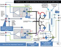
Hi merlin el mago, Scroll down to near the end of the long article that I referenced and there are diagrams that show grounding scheme, more specifically "Example #1 - Split Secondary Rectification with GND Lifter".
It is an example of solid state amplifier with solid state bipolar power supply but the grounding principles still apply.
From http://hifisonix.com/wordpress/wp-content/uploads/2018/07/How-to-wire-up-an-amplifier_3.pdf
It is an example of solid state amplifier with solid state bipolar power supply but the grounding principles still apply.
From http://hifisonix.com/wordpress/wp-content/uploads/2018/07/How-to-wire-up-an-amplifier_3.pdf
Attachments
Last edited by a moderator:
Interesting Jensen paper, not as the usually posted, specially page 13 showing how to test the kind of noise in page 13
http://web.mit.edu/jhawk/tmp/p/EST016_Ground_Loops_handout.pdf
Well, done the test and result is no:
Common-impedance coupling in unbalanced cables (vast majority of problems)
Magnetic or electrostatic pickup by cable of nearby fields
Common-impedance coupling inside defective equipment
Grounding done as attached schematic of Rod Elliot.
Attachments

The diode bridge connection to ground in the diagram that you posted does not agree with the connection shown in the article that I referenced in my posts: Another ground lift connection: DC Servos
This is in agreement with the arrangement shown in my previous post and also as shown in the Valve Wizard article that you referenced in one of your earlier posts.
This is in agreement with the arrangement shown in my previous post and also as shown in the Valve Wizard article that you referenced in one of your earlier posts.
Attachments

The safety ground connection to chassis and the signal ground connection must be two separate chassis connections. On that we should all agree.
The best place to make the signal ground connection depends on all sort of things, so if you are looking for a foolproof recipe I am afraid you might not find it. In the case of a power amplifier the input sockets may be a good place. For a phono preamp it could be the output sockets. For a line stage who knows?
The best place to make the signal ground connection depends on all sort of things, so if you are looking for a foolproof recipe I am afraid you might not find it. In the case of a power amplifier the input sockets may be a good place. For a phono preamp it could be the output sockets. For a line stage who knows?
Thank you very much, your answer let me know all my questions.
N.B. Is a phono preamp so I will chassis grriund at the output RCA signal ground.
Here shows like Rod Elliot schematic:
How to Design and Build an Amplifier With the TDA2050 - Circuit Basics
EasyEDA - A Simple and Powerful Electronic Circuit Design Tool
N.B. Is a phono preamp so I will chassis grriund at the output RCA signal ground.
The diode bridge connection to ground in the diagram that you posted does not agree with the connection shown in the article that I referenced in my posts: Another ground lift connection: DC Servos
This is in agreement with the arrangement shown in my previous post and also as shown in the Valve Wizard article that you referenced in one of your earlier posts.
Here shows like Rod Elliot schematic:
How to Design and Build an Amplifier With the TDA2050 - Circuit Basics
EasyEDA - A Simple and Powerful Electronic Circuit Design Tool
I have used this connection method for 20 years. It is easy and reliable. I happen to have a bag full of X2 caps with 4.7nF value, but anything from 4.7nF to 0.1uF will work well. I would recommend an X2 or Y2 cap for this.
I also ground the earth right at the input RCA signal ground or as close as you can to it.
I also ground the earth right at the input RCA signal ground or as close as you can to it.
Attachments
- Status
- Not open for further replies.
- Home
- Design & Build
- Construction Tips
- Chassis ground