Hi, I've built stereo integrated amplifier based on bridged LM3886 power amps and PGA2310 based preamp. Power amp for each channel is on a separate board. It works fine except annoying hum can be heard from the speakers. I've investigated the problem and found that the reason for this is the ground loop between 2 power amp boards.
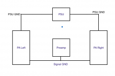
The preamplifier and power amplifier use completely separate power supplies so the only ground connection between them is through the signal ground from the preamplifier to power amps.
It seems that ground loop exists because there is a ground connection between channels on the power wires and another one appears when both channels are connected to preamp. Obviously left and right channel in preamp share the same ground.
I tried disconnecting one channel from the preamp and in this case this hum in another channel is gone.
I've read a lot about ground loops but still don't quite understand how can I solve the problem in my case. The ground connection from PSU to each power amp board is obviously needed and line level source has common ground for left and right channel.
I would appreciate any suggestions on how to solve this problem.
Power amp for each channel is on a separate board. It works fine
except annoying hum can be heard from the speakers.
Raise each of the amplifier's input RCA ground terminals above ground with a 10R resistor.
Last edited:
No the signal wires are not screened. Just a twisted pair of copper wires.
So then how is the signal ground connected to the psu ground? Your 1st pic doesn't show that, although it does show a large loop.
The important thing is that there is a connection, without power supply current running through a wire that also carries signal ground.
Raising the RCA's with 10 ohms to ground as suggested would break the loop.
Jan
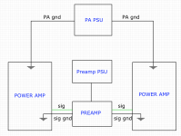
Power amp boards have ground planes so that's the only connection between signal ground and Power amp PSU ground. Preamp and power amp use completely separate power supplies with separate transformers so basically it's 2 devices in one chassis. I've attached a new version of the amp configuration diagram.
How exactly can I lift ground by the resistor? Does it mean that I should try including resistor into signal ground line?
Attachments
Please post some photos of your build and PCB layout. The ground loop is obviously present. Are there transformers placed within the loop or a bad PSU design?
The other thing to try is ground the signal screen on one side only, the RCA side. That will break a loop.
You probably need some ground and that can be done by grounding ONE of the screens at the amplifier side through 10 ohms.
Jan
You probably need some ground and that can be done by grounding ONE of the screens at the amplifier side through 10 ohms.
Jan
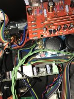
I've tried to change the routing of signal ground. I've routed signal ground from preamp output to Power Amp PSU ground terminal and then from that terminal to Power Amp ground input. Old ground wires I've disconnected from the preamp side leaving them only as shields connected only on the power amp side. This reduced the buzz but not fully.
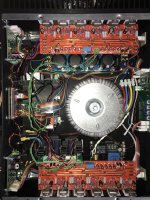
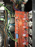
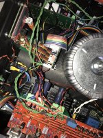
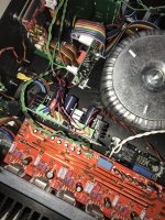
Attaching some photos of my build.
Attaching some photos of my build.
Attachments
Last edited:
I've got the same soft start board as you. How does it sound now? It's the area within the loop that matters too. Keeping the signal wires of both channels close coupled helps.
I've got the same soft start board as you. How does it sound now? It's the area within the loop that matters too. Keeping the signal wires of both channels close coupled helps.
After rerouting signal ground buzz reduced but still can be heard when no music is playing especially from the channel that is located on the other side of the chassis from the PSU.
In my build as you can see each channel board is located on opposite sides of the chassis on the heatsinks so keeping signal grounds for channels close is impossible unfortunately.
Sorry to add another question, but I can see the Mains Earth wire going to the PSU in the first picture. Where do you earth the chassis?
After rerouting signal ground buzz reduced but still can be heard when no music is playing especially from the channel that is located on the other side of the chassis from the PSU.
In my build as you can see each channel board is located on opposite sides of the chassis on the heatsinks so keeping signal grounds for channels close is impossible unfortunately.
If it is buzz, not hum, it is the wiring itself, not the routing. By rerouting you probably changed the wiring which changed things. But with buzz, it is ground currents from the rectified voltage through the wiring, because the wiring for the signal ground carries also the power supply (return) currents.
Jan
You may find the best solution are "hum breaking resistors" as described here pages 4 to 6 https://www.updatemydynaco.com/documents/GroundingProblemsRev1p4.pdf
If it is buzz, not hum, it is the wiring itself, not the routing. By rerouting you probably changed the wiring which changed things. But with buzz, it is ground currents from the rectified voltage through the wiring, because the wiring for the signal ground carries also the power supply (return) currents.
Jan
It's hum of transformer frequency (or double of that). It's intensity changes when I move signal wiring closer to or further from the transformer.
Sorry to add another question, but I can see the Mains Earth wire going to the PSU in the first picture. Where do you earth the chassis?
Main Earth is connected to chassis at that point. That point of PSU pcb is not connected to PSU ground. So at the moment there's no connection between ground and Mains Earth
You may find the best solution are "hum breaking resistors" as described here pages 4 to 6 https://www.updatemydynaco.com/documents/GroundingProblemsRev1p4.pdf
Probably, but unfortunately power amp PCBs that I already have, don't have separate power and signal grounds, they have only one shared ground plane so there's no way to separate it like in this document
If there is no way to modify then insert the resistance into the signal return as mentioned earlierProbably, but unfortunately power amp PCBs that I already have, don't have separate power and signal grounds, they have only one shared ground plane so there's no way to separate it like in this document
... It's hum of transformer frequency (or double of that). It's intensity changes when I move signal wiring closer to or further from the transformer.
... Main Earth is connected to chassis at that point. That point of PSU pcb is not connected to PSU ground. So at the moment there's no connection between ground and Mains Earth
If there really is NO connection between the chassis (mains earth) and your 0 volt ground lines, first thing to try is connecting them together. You need to reference them together or you will 'pick up' any stray fields as 'signals'. Connect a piece of wire or 'croc' clip to the green/yellow wire on the PSU and try connecting the other end to various places on those green ground wires as they loop round, start close to the preamp inputs and work back to the PSU. You may need to try the same test with your 10 ohm resistor in line too. I suspect you will have to plan a better grounding scheme too...
Alan
- Status
- Not open for further replies.
- Home
- Amplifiers
- Chip Amps
- Ground loop problem in integrated amp