Thanks for your quick answer Prasi, but you didn't answer my first question : why every body put the power transistors completely under the PCB ?
Beside that, today double side PCB cost the same than single side and for 5 US$ the pack of 10 there is no more interest to build them our self 😀
Regards, Marc
Beside that, today double side PCB cost the same than single side and for 5 US$ the pack of 10 there is no more interest to build them our self 😀
Regards, Marc
Hello Marc,
Completely under enables more effective utilization of space inside the cabinet as well as on PCB.
If the power transistors are out, although PCB looks small, the area covered by PCB+ Transistor body is the actual real estate used.
So, if transistors are completely under, then you can put components everywhere on the PCB. I am not so good in describing, so please try to imagine.
I would imagine side to side or up and down are more or less equal and again as I said depends upon case you are planning and circuit and number of o/p transistor.
I think there is lot of people still doing home etched PCBs. You should look at Apex 100W ultimate fidelity amplifier thread😀
Take this recent example.
100W Ultimate Fidelity Amplifier
5$ looks very tempting, but dont forget shipping charges, ( paypal charges and local taxes in some cases). If customs decide to work on one fine day, you will be slapped with additional import duties. I got a duty of 35 USD for 2 designs 10 PCB each.
Last edited:
Marc,
here is a superb example of making use of real estate of pcb and case- by vzaichenko and Jwilhelm team .
.
Post your Solid State pics here.
for smd designs, its even better.
Prasi
here is a superb example of making use of real estate of pcb and case- by vzaichenko and Jwilhelm team
.Post your Solid State pics here.
for smd designs, its even better.
Prasi
What is the bias for this amp, I’m ordering the output devices tomorrow but would like to know the approx required C/W of the heatsink for each channel.
Since my load is 4 ohm, is it best to use a +/- 35v supply instead of +/- 45V ?
My output will be a single device, ECX10N20 / 10P20 per channel.
Thanks
Eric
Since my load is 4 ohm, is it best to use a +/- 35v supply instead of +/- 45V ?
My output will be a single device, ECX10N20 / 10P20 per channel.
Thanks
Eric
Aim for around 100ma (for a single pair) which is the optimum point for bias stability for a circuit such as this.
-/+35 volts sounds fine for a nominal 4 ohm load and should be able to deliver around 60 wrms into that impedance. Heatsinks for normal music duty (as opposed to 24/7 sine testing) would be around 0.7C/W. The heatsink requirement is no different to any other AB amp and is usually a compromise between size and cost.
-/+35 volts sounds fine for a nominal 4 ohm load and should be able to deliver around 60 wrms into that impedance. Heatsinks for normal music duty (as opposed to 24/7 sine testing) would be around 0.7C/W. The heatsink requirement is no different to any other AB amp and is usually a compromise between size and cost.
What is the bias for this amp, I’m ordering the output devices tomorrow but would like to know the approx required C/W of the heatsink for each channel.
Since my load is 4 ohm, is it best to use a +/- 35v supply instead of +/- 45V ?
My output will be a single device, ECX10N20 / 10P20 per channel.
Thanks
Eric
Eric,
Have you ordered the Exicon devices?
Project16 had shared a source for 2SJ162 and 2SK1058 in his earlier post on this thread:
https://www.diyaudio.com/forums/sol...-amplifier-designed-music-75.html#post5547478
Mooly,
Is there any advantage in going for the newer Exicon devices? Or you would reckon if still available, the 2SJ162 and 2SK1058 would better suit the design.
I wouldn't foresee any problems with using the newer lateral devices tbh and I've never heard of any issues (on any amplifier) from those doing the swap.
I have no problem if any of you want to produce PCB's and sell them as a group buy 🙂
Hi Mooly
Since you didn’t mind, I sent the Gerber files to PCBWAY and got them back today.
Special thanks to you and Prasi !
BR
Eric
Attachments
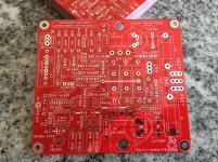
Hi Mooly
Since you didn’t mind, I sent the Gerber files to PCBWAY and got them back today.
Special thanks to you and Prasi !
BR
Eric
Nice red PCBs Eric - assuming you got a few extra boards? 🙂 If yes, how much would it be for a pair?
Last edited:
If I remember correctly the cost was $15 usd delivered to my door so 1.5 usd per pcb.
So basically $3 usd for a pair + price of padded envelope + shipping
I do not intend to start a GB but I’ll sell at cost 3 pairs.
BR
Eric
So basically $3 usd for a pair + price of padded envelope + shipping
I do not intend to start a GB but I’ll sell at cost 3 pairs.
BR
Eric
If I remember correctly the cost was $15 usd delivered to my door so 1.5 usd per pcb.
So basically $3 usd for a pair + price of padded envelope + shipping
I do not intend to start a GB but I’ll sell at cost 3 pairs.
BR
Eric
Eric,
I'm in. 🙂
Ok so 1 set for Zman01 and 1 set for Spind
Pcb is 100mm x 92mm, 1oz and un-tested so at your own risk.
BR
Eric
Pcb is 100mm x 92mm, 1oz and un-tested so at your own risk.
BR
Eric
Question for Prasi 🙂
Prasi,
First of all thanks for your efforts in coming up with different versions of the PCB layout.
With reference to your earlier post, I have a few questions:
1. The new 92mm x 100mm PCB has fewer parts that your perviously published 100mm x 100mm PCB?
2. When you say "compromised" and "reduced" what exactly do you mean?
Hello Mooly,
If a 2U case such as the one (dissipante) available from diyaudio store to be used, the width of PCB needs to be less than 80mm. This got me thinking that I need to reduce width at the same time keep the length to less than 100 mm to take advantage of PCB costs from China. Many compromises had to be made to achieve this.
So I came with the attached plan of layout, by reducing component package options . It would be challenging to fit components and solder them, but should be doable if care is taken and properly planned.
Prasi,
First of all thanks for your efforts in coming up with different versions of the PCB layout.
With reference to your earlier post, I have a few questions:
1. The new 92mm x 100mm PCB has fewer parts that your perviously published 100mm x 100mm PCB?
2. When you say "compromised" and "reduced" what exactly do you mean?
zman01,
I think you already booked PCBs from Eric so build that. You have the BoM already for that version.
If you are asking for your understanding purpose, I suggest you print stuffing guides of both versions and compare for yourself😉 It will be a good exercise.
I think you already booked PCBs from Eric so build that. You have the BoM already for that version.
If you are asking for your understanding purpose, I suggest you print stuffing guides of both versions and compare for yourself😉 It will be a good exercise.
- Home
- Amplifiers
- Solid State
- My MOSFET amplifier designed for music