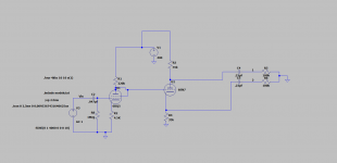
So I was playing around in LTspice (still a newbie with this program), mostly just experimenting, and this design does seem to measure quite well. Around .14% distortion at 100V P-P output (Around 35V RMS). At 60V P-P, it has .05% distortion.
The catch is, the 6BQ5 is operating at about 1.3 mA. The 6SN7 is operating at 3.5 mA. 1.3mA is tiny for a 6BQ5, and it has a much higher plate resistor than I could have possibly expected to perform well.
Just out of curiosity, does this seem like an ill-advised design? I believe that it can swing enough voltage to drive a 6L6 to full power, and it doesn't have a huge amount of gain, only about 11. IMO, this is a good thing.
I'm very interested to hear about how realistic the simulated performance is, in this case, and if it would just be too vulnerable to noise issues. After all, the 6BQ5 wasn't exactly designed as a preamp tube.
Thanks for the feedback on this kind of thing, I'm trying to continue learning what I can about this stuff even though I won't be able to actually build much until winter break when I come home. At the time being, LTspice is where this is at. Attached is an image of the design, the LTspice schematic and the necessary models file.
-H713
Attachments
Have you tried using the 6SN7 into the 6BQ5 connected as a triode running hotter? Probably less distortion and more P-P output that way?
I would not trust the SPICE model at current SO far below normal operating zone.
It will work, but probably not the same as SPICE thinks.
You could, as said, run the 6BQ5 at much higher current. When driving a *load*, this is often better. But the cathodyne is nearly no load at all.
You can buy MUCH cheaper triodes than 6BQ5; why use that?
It will work, but probably not the same as SPICE thinks.
You could, as said, run the 6BQ5 at much higher current. When driving a *load*, this is often better. But the cathodyne is nearly no load at all.
You can buy MUCH cheaper triodes than 6BQ5; why use that?
The challenge here may be my requirement. I would like this to have a gain of around 10 or 15, and still be able to swing somewhere around 40 volts RMS, enough to drive a 6L6 properly.
I am wanting to play with some less expensive pentode tubes run as triode, like the 12HL7 and 12CA5, but finding spice models for these tubes is not always easy, and as of right now I don't quite have the understanding of LTspice to be able to create my own.
I am wanting to play with some less expensive pentode tubes run as triode, like the 12HL7 and 12CA5, but finding spice models for these tubes is not always easy, and as of right now I don't quite have the understanding of LTspice to be able to create my own.
Of course it will.
I've used 6BQ5 (6P14P, actually) and 6P15P as triode-connected drivers before, and found that it wasn't worth the extra heater power, but the 6P15P made a better driver tube, lower THD at 100 volt signal output. The same can be done easily with a 6SN7 with comparable or lower distortion, given adequate supply voltage.
I've used 6BQ5 (6P14P, actually) and 6P15P as triode-connected drivers before, and found that it wasn't worth the extra heater power, but the 6P15P made a better driver tube, lower THD at 100 volt signal output. The same can be done easily with a 6SN7 with comparable or lower distortion, given adequate supply voltage.
Last edited:
If you want more of linear swing, use 6P15P. But of course not with 220K load, that would be probably fine for 6J5P tube, or even for 6J4P.
The challenge here may be my requirement. I would like this to have a gain of around 10 or 15, and still be able to swing somewhere around 40 volts RMS, enough to drive a 6L6 properly.
Are you going to have 4v of input signal to it?
But will it swing around 40 volts RMS without major distortion?
Why wonder?
60+ years ago some junior engineer sweated over a hot 6SN7 to compile performance data for your convenience.
Generally the larger G.E. sheets have Resistance Coupled Amplifier tables (for tubes where that is an obvious use; not 6BQ5.)
http://www.mif.pg.gda.pl/homepages/frank/sheets/093/6/6SN7GTB.pdf
Are you going to have 4v of input signal to it?
This amp will be paired with a poorly-planned preamp project from this spring. I was a moron who did not listen to opinions from numerous prominent members here, and it has a bit too much gain for most amps. It can happily swing 4 volts.
Why wonder?
60+ years ago some junior engineer sweated over a hot 6SN7 to compile performance data for your convenience.
Generally the larger G.E. sheets have Resistance Coupled Amplifier tables (for tubes where that is an obvious use; not 6BQ5.)
http://www.mif.pg.gda.pl/homepages/frank/sheets/093/6/6SN7GTB.pdf
Thanks, the RCA 6SN7 datasheet I've been using for ages is nowhere near that comprehensive. Am I reading it right that with a 300V supply It suggests a 100K plate resistor with something like a 1.8K cathode bias resistor?
Last edited:
Am I reading it right that with a 300V supply It suggests a 100K plate resistor with something like a 1.8K cathode bias resistor?
Yep. Keep in mind, that those output values assume a fully bypassed cathode resistor to achieve that level of gain and output. When you build it, you can measure the voltage on the cathode resistor, and replace the resistor with a string of LEDs or diodes dropping the same voltage, to get higher gain at lower distortion than a capacitor bypass. Without a bypass you may only get ~60% of the quoted gain.
If you have higher supply voltage available, scale the values accordingly and you'll get a smidge higher gain and a smidge lower distortion. a 350~400 volt supply would be nice for these tubes for sure, but 300 will work. If running a higher supply for the output stage it'll be easy to run the 6SN7 off it as well with adequate filtering.
You might find the Thorsten Legacy amp an interesting read:
http://community.fortunecity.ws/rivendell/xentar/1179/projects/legacy/Legacy.html
SpreadSpectrum has also done some cool experiments with EL84 as a driver, documented on his blog:
Tube Amps with a Twist
http://community.fortunecity.ws/rivendell/xentar/1179/projects/legacy/Legacy.html
SpreadSpectrum has also done some cool experiments with EL84 as a driver, documented on his blog:
Tube Amps with a Twist
Yep. Keep in mind, that those output values assume a fully bypassed cathode resistor to achieve that level of gain and output. When you build it, you can measure the voltage on the cathode resistor, and replace the resistor with a string of LEDs or diodes dropping the same voltage, to get higher gain at lower distortion than a capacitor bypass. Without a bypass you may only get ~60% of the quoted gain.
If you have higher supply voltage available, scale the values accordingly and you'll get a smidge higher gain and a smidge lower distortion. a 350~400 volt supply would be nice for these tubes for sure, but 300 will work. If running a higher supply for the output stage it'll be easy to run the 6SN7 off it as well with adequate filtering.
That's the trick. I noticed that it shows these specs at 5% distortion, which is a lot more than I'd like. I'd really like to be down below 1% if possible. I do have a 430 volt supply in the amp, but it's for the power tubes. I had planned on using the 300V regulated screen supply for the 6SN7s.
Wrap some feedback around it all. Should do nicely. You've got a hot enough source anyway, the reduced input sensitivity wont matter.
That's the trick. I noticed that it shows these specs at 5% distortion, which is a lot more than I'd like.
You will find these kind of 5% THD numbers on most of the "better" old school datasheets. They are handy if you are building the PA system for an auditorium, etc.
They do not indicate that this tube/valve gives 5% distortion across the board. Not by a long shot. They only indicate how far you can push the valve/tube before you get 5% distortion...
That "Eo" value (at the bottom of page 3) is Maximum RMS for 5% THD (with cathode by-passed). No idea what the input signal was for each of these given values...
The "Gain" value is shown for 2.0 VRMS output. "Esig" must obviously be adjusted accordingly (i.e. attenuated down) to obtain this value.
So it seems that "Eo" and "Gain" values are not values measured simultaneously. They are simply values reported in a chart for a given value of Rk. At least that is how I interpreted such charts. Kind of useless information for us today imho... but they are really useful if you don't have computers to make calculations, spice models, etc.
Also, don't forget that the cathode is by-passed in this circuit. you can use a non-bypassed cathode for lower gain and less distortion. Just make sure the load (and B+) is high enough for adequate low frequency response. 😉
maybe look at these old measurements from Pet Millett too to see how THD might be different depending on measurement conditions:
Current Source
Ian
Last edited:
...Am I reading it right that with a 300V supply It suggests a 100K plate resistor with something like a 1.8K cathode bias resistor?
Yes, _IF_ the next stage load is 0.10Meg. However you are driving a cathodyne? The input is typically much higher, Meg or more. On this chart you drop to lines with high "Rs". p=0.24M Rs=0.51M offers 54Vrms output.
(The zero-bias lines, Rg1=10Meg, offer even more. This suggests the Rk values are not fully optimized FOR output, and a smaller Rk may gain more output.)
Also look across 90V 180V 300V. Max output rises with supply, nearly linearly. You can scale-up above 500V, more output, or lower THD for the same output.
...5% distortion, which is a lot more than I'd like. I'd really like to be down below 1% if possible....
40Vrms to swing a 6L6 does not sound right, unless you are setting G2 near 1000V. For 300V G2, bias should be near -18V, so peak swing is 18V, or 13V RMS.
You can't always get all you want.
Consider: a perfect device, resistor feed, no load, 300V, can swing 300V/2.828 or 106V RMS. 6SN7 has significant internal resistance and can not swing so far.
To get that 106V swing the device current must go from some maximum down to ZERO. But device transconductance always varies with current (to zero at zero current). BJT Gm varies directly as current, and just below clipping (an ill-defined thing in such a hard-driven stage) the THD gets to 26%. Tubes in their "normal" zone have Gm about as square-root of current, so make about 5% THD, though at a lesser (relative to supply) clipping point.
With typical loading, a tube will make a Peak swing about 20% of supply. (Check: 6SN7 will make 40V-51V RMS or 56V-71V peak from 300V: peak near 19%-24% of supply.) And will be around 5% at this point.
THD will drop roughly linear with output. If 5%THD @ 51Vpeak, under 2% at 18V peak.
All of this is not new news.
Topology is one answer. While I think your gain-cathodyne is the best plan for your needs, you could do a long-tail for about the same parts. The single-ended stages (well biased) make 2nd-order distortion. A push-pull driver first-order *cancels* all this.
Back in the 1930s several guys developed Negative Feedback to cause an amplifier to self-correct its own output. Excess gain is much easier to find than massive clean output. Build a not-too-dirty amplifier, with excess gain, and let it clean itself up. In this case I would turn to 12AX7, gain of 50, 15X more than needed. That would cut 2% in driver down to 0.2%, or 5% total down to under a half %. It also damps your speaker-- the 6L6 was a hard-sell at first because it didn't damp loudspeakers like the triodes did.
- Status
- Not open for further replies.
- Home
- Amplifiers
- Tubes / Valves
- Triode-mode 6BQ5 as input tube?