If my calculation is correct this is the formula of the gain (C2 is ignored)
A(p) = (p*(R3*R4 + R3*R5 + R4*R5)*C1 + R4) / (p*(R3*R5 * R4*R5)*C1 + R5)
Where p = 2*pi*f*j (j is imaginary one or sqrt(-1))
So there are two imoprtant frequencies: one pole and one zero
Pole freq is 1 / (2 * pi * Re1 * C1)
Zero freq is 1 / (2 * pi * Re2 * C1)
Where:
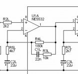
Re1 = (R3+R4)
Re2 = (R3*R4+R3*R5+R4*R5)/R4
A(p) = (p*(R3*R4 + R3*R5 + R4*R5)*C1 + R4) / (p*(R3*R5 * R4*R5)*C1 + R5)
Where p = 2*pi*f*j (j is imaginary one or sqrt(-1))
So there are two imoprtant frequencies: one pole and one zero
Pole freq is 1 / (2 * pi * Re1 * C1)
Zero freq is 1 / (2 * pi * Re2 * C1)
Where:
Re1 = (R3+R4)
Re2 = (R3*R4+R3*R5+R4*R5)/R4
For the given values, pole is @38Hz and zero is @483.6Hz. Close to values specified by RIAA 50Hz and 500Hz.
thanks, this is amazing. i put it in an excel sheet and now know how to adjust values to get closer to RIAA values.
may i ask how you know how to calculate this? i would never have been able to figure it out.
may i ask how you know how to calculate this? i would never have been able to figure it out.
So that basically means that with the current values bass rolls off to "late" at 38Hz instead of 50Hz, right?
The reason I ask is because on another forum people seemed to have complained about excess woofer movement and the solution seemed to be a 130k resistor instead of the 180k. According to the formula this would move the rolloff to 51,7Hz and I guess that explains why there'd be less bass. Is my thinking right on this?
I did play with some other values and found that choosing 133k for R4 and 4k12 for R5 (all other values unchanged) gives a pole at 50.6Hz and a zero at 501.35Hz which is a lot closer to RIAA than the original design. The mentioned values are available as 0,1% resistors from vishay.
Mixi, this type of analysis of electric circuit is part of the EE studies at university.
I'll try in short to explain how this formula is derived. Let R5 and C2 are replaced with impedance Z1, and R3, R4 and C1 are replaced with impedance Z2.
Formula for closed loop gain (assuming op-amp has very high open loop gain) is A = (Z1 + Z2) / Z1
If we ignore C2 then Z1 = R5
On the other hand Z2 is consisted of parallel connection of two branches: first is the branch with R4, other is the branch with C1 and R3.
Therefore Z2 = R4 || (1/pC1 + R3).
So Z2 = R4 || ((pR3C1 + 1) / pC1)
Z2 = R4 * (pR3C1 + 1) / (p*(R3 + R4)*C1 + 1)
By replacing Z1 and Z2 in the formula for closed loop gain we finaly get
A(p) = (p*(R3*R4 + R3*R5 + R4*R5)*C1 + R4) / (p*(R3*R5 * R4*R5)*C1 + R5)
From recollection (decades ago 🙂 ) , frequencies for which modulus of the expression in the denominator becomes 0 are poles.
Similarly, frequencies for which modulus of the expression in numerator equals 0 are zeroes.
Pole is yielded from:
2*pi*f*(R3*R5 * R4*R5)*C1 = R5
Zero is yielded from:
2*pi*f*(R3*R4 + R3*R5 + R4*R5)*C1 = R4
The reason I ask is because on another forum people seemed to have complained about excess woofer movement and the solution seemed to be a 130k resistor instead of the 180k. According to the formula this would move the rolloff to 51,7Hz and I guess that explains why there'd be less bass. Is my thinking right on this?
Excess woofer movement means presence of significant subsonic content. This may be result of cartridge / tonearm mismatch or badly wrapped records. C2 and R5 are responsible for subsonic filtering. The formula is
f = 1/(2*pi*R5*C2)
Presented values make for relatively poor subsonic suppression. So one can try decreasing C2 value to 5u6 for example. Beware, too high subsonic filter may weaken bass reproduction.
Last edited:
Thank you very much for your explanation and for sharing your knowledge!
Are you sure the electrolytics C2 and C3 are intended as a rumble filter?
I understand that the formula you provided would put the roll off frequency at 1,5Hz which would not make any sense for rumble filtering. With the values you suggested the roll off would be moved to 6Hz which i guess would make more sense.
But this is what the designer says: "The AC voltage across C2L/R and C3L/R will never exceed ~5mV at any frequency down to 10Hz, and these caps play no part in the equalisation process. Feel free to increase the value if you wish (100µF is not a problem)."
At 100uf the rolloff would be at 0,33Hz so hardly effective as a rumble filter I assume.
But if those caps don't serve as filters, what is their purpose in this spot?
All the details are here: Rod Elliott Phono Preamp
The electrolytics are there to ensure that the opamp has unity DC gain, so offsets do not build up.
The electrolytics are there to ensure that the opamp has unity DC gain, so offsets do not build up.
This is the original function of these caps. Higher values would insure these capacitors (electrolytics are considered inferior for audio) do not interfere audio band signal, yet remain effective in blocking input DC offset.
However it is possible to repurpose them as subsonic filters by reducing their value hence increasing roll-off frequency (optimal value can be determined by experiment). In that case, it is advisable (and feasible) to use some more audio-filter-friendly film types (polyprops are recommended, although good MKT may be good enough).
Another way to implement subsonic filtering is to introduce capacitive coupling between stages. Serial capacitor C from the output of the first stage (pin 1) to the + input of the next stage (pin 3), plus a resistor R from + input to ground. In that case:
f = 1/(2*pi*f*R*C)
R should equal R6, that is 100k. So a polyprop C=150nF would set high pass filter at 10.6Hz.
Again, thanks for the valuable information!
Regarding DC in the circuit. If i understand it right the goal is to keep DC away from the signal. And the only way DC could get to where it's not supposed to be is via the power ground (because the power supplied to the Opamps is DC). Is that correct?
So the electrolytic help to keep dc from the input of the amp?
On a different note: I keep reading references to the Lipschitz RIAA paper. Anybody know where I can get a copy?
Regarding DC in the circuit. If i understand it right the goal is to keep DC away from the signal. And the only way DC could get to where it's not supposed to be is via the power ground (because the power supplied to the Opamps is DC). Is that correct?
So the electrolytic help to keep dc from the input of the amp?
The only source of DC on the input is the imperfection of the op-amps. It's the input offset voltage of the used specimen. Ideal opamp should have 0V input offset. Often it's few mV with real world chips. The effect is equal as if a miniature battery of the same voltage is connected in series to the input.
RIAA preamps have typically A=1000 at low frequencies. This would extend to DC without the mentioned caps (if replaced by links). So let say a 5mv input offset of the first opamp would end as 5V DC offset at the output of the second stage hence reducing the available output voltage swing (headroom). With this caps DC gain is 1.
rfbrw lists the papers here: https://www.diyaudio.com/forums/analogue-source/21572-calculate-riaa-correctly.html#post250842
As BrianL hinted, you can buy from AES.
Or use google and see what you find ...
mlloyd1
As BrianL hinted, you can buy from AES.
Or use google and see what you find ...
mlloyd1
found a preview on a site that came up as a google search. i doubt that my math skills are good enough to understand the article .... :-(
chip_mk: thanks for the explanation! i have build a few RIAA amps with similar topology by now and interestingly this is the first one that uses caps in this location. is it just an added safety measure or could there be another reason why other designers omitted it?
chip_mk: thanks for the explanation! i have build a few RIAA amps with similar topology by now and interestingly this is the first one that uses caps in this location. is it just an added safety measure or could there be another reason why other designers omitted it?
this info from a former member is helpful:
Phono Preamp Design Using Active RIAA Equalization
mlloyd1
Phono Preamp Design Using Active RIAA Equalization
mlloyd1
fantastic article, thanks! even i can follow the math if it's explained in such kind of detail.
interestingly the topology includes an additional resistor R4 which i think isn't present in the original Lipschitz paper.
interestingly the topology includes an additional resistor R4 which i think isn't present in the original Lipschitz paper.
the topology includes an additional resistor R4 which i think isn't present in
the original Lipschitz paper.
That's an attempt to boost the extreme highs to compensate for cutting lathe roll off,
not such a good idea.
Last edited:
Better idea than you might think... less so for the ultrasonic pole but rather for keeping a minimum gain (for non-unity-gain-stable OPs) and not having the OP break a sweat trying to drive R3 directly (imagine you've got 470R or below and a wimpy 4558), not to mention input capacitance.
...having the OP break a sweat trying to drive R3 directly....
not to mention input capacitance.
The opamp won't face R3 directly until like >50KHz. There is hardly any signal from MM needle by 50KHz. While a TL072 (4558? Seriously??) is kinda lame with 470r load, it still has ~~half its unloaded gain and will not do anything rude.
Not sure why you do not want to mention input capacitance?
- Home
- Source & Line
- Analogue Source
- RIAA calculation help needed