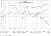
added the ports, low end is better, but I think room nodes where I am testing are making it appear less good than it is. I also am not sure about testing 3 ft from the tweeter when the port is then 2.5 ft lower than the tweeter.. It sounds much better 15 ft away in listening area. Graph is as similar measuring setup as possible in my master bedroom, tons of furniture and even me sitting right behind the mic lol. Comparison you can see the low freq gains but the whole rest is all over the place up and down. I need to measure outside in open air and then try the DSP with the REQ settings applied into it.
Attachments
Last edited:
That may be the biggest problem we all face. Getting a decent measurement.
Even at 1m you should be seeing more bass, its omnidirectional. What does your sim model predict ? Possible causes: your enclosure might be leaking or tuning is off or narrow baffle causing loss (baffle step).
Even at 1m you should be seeing more bass, its omnidirectional. What does your sim model predict ? Possible causes: your enclosure might be leaking or tuning is off or narrow baffle causing loss (baffle step).
Last edited:
Design comparisons
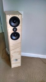
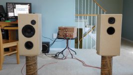
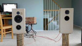
I have my two designs setup (pic#1) and compensated for the differences in sensitivity. I noticed the 2-way (left side) did not sound clean, or at least less so than the full range (right side) and starting looking into it.
I should point out that both these drivers are capable of -50db THD when connected straight to an amp. The distortion rise from the budget XO can be noticed in the woofer LF+MF bands as well.
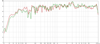
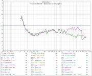
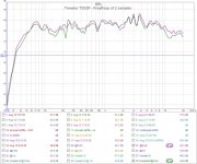
Notice the FR for the 2 tweeter samples (graph#1) is virtually the same and you would never suspect a problem. If you look at the distortion (graph#2) you can see one of the 2 samples is not working properly. I marked the good tweeter and swapped several times to be sure.
I have my two designs setup (pic#1) and compensated for the differences in sensitivity. I noticed the 2-way (left side) did not sound clean, or at least less so than the full range (right side) and starting looking into it.
I should point out that both these drivers are capable of -50db THD when connected straight to an amp. The distortion rise from the budget XO can be noticed in the woofer LF+MF bands as well.
Notice the FR for the 2 tweeter samples (graph#1) is virtually the same and you would never suspect a problem. If you look at the distortion (graph#2) you can see one of the 2 samples is not working properly. I marked the good tweeter and swapped several times to be sure.
Attachments
Last edited:
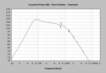
My sims are attached.
Sealed ( before I put the port in)
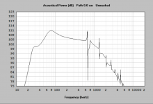
Ported (with the designed weird curve to work well with EQ)
Target after EQ
I planned to rely heavily on EQ to get the response flattened. I had forgotten how close the curve still is to the sealed box... They do have a lot of bass, in fact, an astonishing amount for a $30 pair of speakers! I am shocked excursion is not an issue as the simulation shows it getting pretty out of hand below 40 hz. For the EQ sim I was targeting the rated 3.5mm but maybe that is too conservative?
I will not be able to hit my EQ targets in budget, but I might be able to get at least the pam8403 5w amp and DSP within budget to flatten things. unsure how to get the EQ points though as from my understanding the DSP can do hundreds of points but room EQ only seems to do 20...
Sealed ( before I put the port in)
Ported (with the designed weird curve to work well with EQ)
Target after EQ
I planned to rely heavily on EQ to get the response flattened. I had forgotten how close the curve still is to the sealed box... They do have a lot of bass, in fact, an astonishing amount for a $30 pair of speakers! I am shocked excursion is not an issue as the simulation shows it getting pretty out of hand below 40 hz. For the EQ sim I was targeting the rated 3.5mm but maybe that is too conservative?
I will not be able to hit my EQ targets in budget, but I might be able to get at least the pam8403 5w amp and DSP within budget to flatten things. unsure how to get the EQ points though as from my understanding the DSP can do hundreds of points but room EQ only seems to do 20...
Attachments
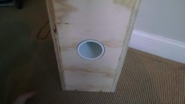
If you do a limited (20Hz-200hz) near field FR measurement of the port and then the lower driver you should be able to tell if its working properly (ie. no leaks). There should be a defined FR dip at the driver that corresponds to a defined FR peak at the port. If you add them in REW you should see the same response as HornResp.
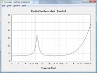
Alternatively, if you're setup to measure the impedance of the speaker you will see 2 peaks and the box tuning is midway between them.
Alternatively, if you're setup to measure the impedance of the speaker you will see 2 peaks and the box tuning is midway between them.
BP6 + FR
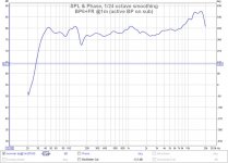
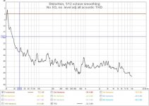
I've been listening to both designs and focusing on the BP6 (right side, pic#1). The BP6 has some mid band residue from the port that could have been reduced if I put the port and fullrange driver on opposite sides. The problem could also be fixed (checked in Xsim) with a 1st or 2nd order LP filter on the BP6 @600Hz. Instead I'm temporarily using an active bandpass to eliminate the midband residue and balance the driver sensitivity differences for testing.
The speaker FR and THD are shown in the graphs. The bass is excellent, but I am biased, and like the sound from series tuned BP6. The full range is another issue. There is nothing wrong with the swept sine measurement or the THD measurements. The peak at 13Khz-17Khz could be notched down to make the FR flatter but it doesn't bother me.
The problem occurs when the fullrange is moving alot (> +/-2mm) during music content with bass. It seems to go muddy, loose clarity and detail. I was listening at moderate levels (90dBc @1m measured) and every time there was significant LF, you could see the driver flapping, and hear the detail fade. I should try a superposition signal test [0db@80Hz plus -10db@1Khz plus-20db@5Khz] to see if it can reproduce the detail when following higher amplitude LF.
Attachments

Last edited:
The 13Khz spike probably wouldn't worry me either, since that's about the limit of my high frequency response these days, but it may bother my daughter 😀
I'm not surprised at all about your comment on the full ranges when there is bass. There was a quite noticeable improvement in clarity of the midrange of my MTM's (using morel MW144 woofers) when I changed them from running full range to being actively crossed over to my Vifa 10" woofers at 270Hz 4th order acoustic. I wasn't expecting that, I was only expecting to get more bass, since the MW144's are sealed and 5L each, with a -3db point around 90Hz).
Tony.
Good to know that effect was not just in my implementation.
Well, it was an interesting experiment to see what might work. This design will be around for another week or so then the drivers and most of the box will be re-purposed for another design. I think that PC83 full range will make a good midrange.
Well, it was an interesting experiment to see what might work. This design will be around for another week or so then the drivers and most of the box will be re-purposed for another design. I think that PC83 full range will make a good midrange.
Morel (and Dynaudio) woofers were big disappointments back in my driver buying days in the 20th century. Short x max...Madisound says 3.5 mm "peak" in their listing. Scanspeak never let me down.
Reducing xmax by shortening the coil can have benefits in an overhung design because it reduces Le(x). Makes it less capable as a woofer but cleans up the midrange.
With the MW144 being a 5" driver I would think that midrange duty is it's primary target anyway (which was always my intention). I was just surprised that what was already very good midrange got even better when it was high passed at 270 Hz.
Tony.
Tony.
I think it is too early to give up on this very ingenious design. If it were my project, I would try the following.
1. Shrink the front volume of the BP6 to raise the cutoff. This could be done in conjunction with absorption for the midrange frequencies.
2. Shrink the volume of the fullrange enclosure and add an aperiodic vent. This will reduce the excursion at resonance and smooth the impedance response.
3. Add a capacitor in series with the fullrange to further reduce the excursion below the cutoff frequency. a bypassed electrolytic would be the most cost effective.
I think it is too early to give up on this very ingenious design. If it were my project, I would try the following.
I'm open to suggestions,.... so I'll put the chainsaw down.😉. You have a couple of ideas worth exploring. Thanks.
1. Shrink the front volume of the BP6 to raise the cutoff. This could be done in conjunction with absorption for the midrange frequencies.
The BP6 can be tuned a little higher using the ports. Unfortunately, reducing the volume will cause it to peak near the roll off points. I can reduce the midband residue using acoustic measures like redirecting the front port and damping (acoustic tile and filling). Even a low cost 1mH series inductor would tame the MF residue. This part is not a problem.
2. Shrink the volume of the fullrange enclosure and add an aperiodic vent. This will reduce the excursion at resonance and smooth the impedance response.
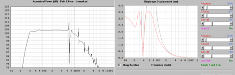
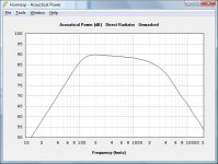
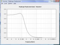
The fullrange displacement is the fundamental problem in the design and its inherent. You can change the chamber volume but you'll still get the excess LF displacement. I've added a few pics for what's happening at 90dB (4watts@PC83), the hornresp displacement measure is peak (mm).
3. Add a capacitor in series with the fullrange to further reduce the excursion below the cutoff frequency. a bypassed electrolytic would be the most cost effective.
I would need a very large series bipolar electrolytic to get a HP@150Hz. I've got about $10 left in the budget for any XO passives.
The aperiodic vent (filled vent) seems interesting and I'll look into it because I've never used or modelled them before. It would be nice to have an acoustic means of limiting the PC83 LF displacement.
Attachments
Thrift stores always have passive subs which usually have satellite outputs. Often a source of 200 uf caps and ferrite core coils for cheap - even a decent pair of drivers sometimes. I put a Pioneer pair in my dcm freebies that worked just fine. That sub cost $5
The steps I outlined were intended to work together. Just using a capacitor on the fullrange would not be effective due to the large impedance peak at resonance. The aperiodic vent will reduce the excursion at resonance, but increase it below, It will also push the f3 higher. The combination of both vent and cap will significantly reduce the displacement, but you will need to have more output from the bandpass between 150-200Hz. A 100uF NP (~200Hz) will cost you $1.50 , pair that with a 10 to 20 uF film cap and still be under $10.
BP6 with filters
Originally when started this design I wanted to see if I could get away no electronic XO and do it all acoustically. It does work but there are some SQ issues. Out of curiosity, I tried playing around with XO filters to see if it's possible to fix some of these SQ issues.
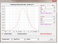
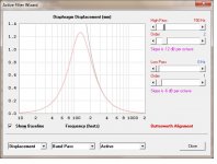
Below are the Xsim pics for a filter and their response. Good news: there is a way and the final response looks close to what I have already. Bad news: it requires passive components that are way too large and expensive, so it's not happening.
Ideally (as suggested @drewmc) if I crossed at the higher freq (>200Hz) the driver displacement will be reduced (pic#5 xo@300Hz). Unfortunately, I can't shrink the full range's chamber volume that small and I can't convince the BP6 to go that high. The pics (#1-#4) are for 90db (4watt), with XO=150Hz. Still looking for an acoustic solution.
Originally when started this design I wanted to see if I could get away no electronic XO and do it all acoustically. It does work but there are some SQ issues. Out of curiosity, I tried playing around with XO filters to see if it's possible to fix some of these SQ issues.
Below are the Xsim pics for a filter and their response. Good news: there is a way and the final response looks close to what I have already. Bad news: it requires passive components that are way too large and expensive, so it's not happening.
Ideally (as suggested @drewmc) if I crossed at the higher freq (>200Hz) the driver displacement will be reduced (pic#5 xo@300Hz). Unfortunately, I can't shrink the full range's chamber volume that small and I can't convince the BP6 to go that high. The pics (#1-#4) are for 90db (4watt), with XO=150Hz. Still looking for an acoustic solution.
Attachments
-
 bp6 with 2nd order xo@300hz 4watt displacement.jpg71.9 KB · Views: 89
 -
 bp6 with 2nd order xo@150hz 4watt displacement.jpg69.9 KB · Views: 90
 -
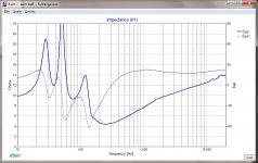 bp6 with 2nd order filters impedance.jpg180.3 KB · Views: 100
 -
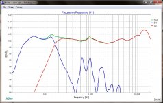 bp6 with 2nd order filters bode.jpg169.8 KB · Views: 218
 -
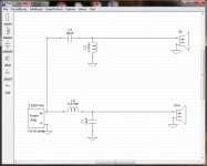 bp6 with 2nd order filters schematic.jpg186.9 KB · Views: 233
BP6 + fullrange, all acoustic no XO
I've been thinking some more about the suggestions from @drewmc.
The fullrange chamber has been reduced to approx 0.3L. The chamber was completely filled with polystyrene blocks and polyester fill. The rolloff starts at nearly 180Hz now.
The BP6 front chamber was reduced by approx 4L using polystyrene blocks. The wall in front of the TC6028 driver has acoustic tile to absorb MF. The front chamber has approx 30% poly fill and the rear chamber has 80% poly fill. The front port elbow was rotated to point away from the driver to reduced MF coupling. All of these changes attenuate the MF residue, raises the upper rolloff point causing a hump, and softens the lower rolloff edge. The LF level is still slightly (2-3dB) higher than the full range so it "appears" to meet (cross) at a higher frequency.
At my listening level (+90dBc @1m) the full range driver is only moving +/-1mm during content with LF bass. It's no longer flapping about, and the detail is back. I'm sure the problem would return at 96dB, but then that's probably unrealistic from a 3" full range driver. I still have some BP6 residue at 800Hz, which could be solved by putting the port and driver on opposite or perpendicular sides. Both drivers are driven at the same electrical level straight from an amp, there is no XO, there is no level adjustment, its all acoustic. It sounds good.
Attachments

I'll admit that as 9/1 gets closer, I'm excited to see what emerges in the wicked-clever under-$40 category. I'm looking for some office/desk speakers in that ballpark and I wonder if any of the designs that come out of this will be accessible to new builders.
It looks like some people are using deeply hoarded parts from old buyouts, so I wonder if we'll all be able to play along when things get done?
It looks like some people are using deeply hoarded parts from old buyouts, so I wonder if we'll all be able to play along when things get done?
I'll admit that as 9/1 gets closer, I'm excited to see what emerges in the wicked-clever under-$40 category. I'm looking for some office/desk speakers in that ballpark and I wonder if any of the designs that come out of this will be accessible to new builders.
It looks like some people are using deeply hoarded parts from old buyouts, so I wonder if we'll all be able to play along when things get done?
It's suppose to use parts you can actually buy, or provide the equivalents that you could buy and provide a current web price.
I was hoping to see more intermediate efforts and discussion rather than just a data dump on 9/1. It may be a quiet 9/1 unless people are holding their designs close to the chests.
- Status
- Not open for further replies.
- Home
- Loudspeakers
- Multi-Way
- silk purse from sows ear contest?