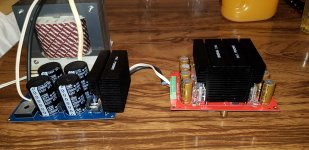
Hi everyone! I've been working a while with this project and now it's working with some great power.
BUT I come to you for advise, since i've encountered some noise issues in the output. There is some hiss in the output that is independent on the input volume.
If a short the input to ground it dimishes a little but it's still clearly audible nonetheless. I've also added 0.1uF and 1uF capacitors in the DRV134 power supply with no improvement. I've also tried adding a 1K resistor between the signal and ground, didn't help eigther.
Thanks in advance. 🙂
Attachments
Last edited:
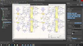
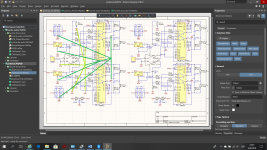
The schematic *seems* to show 20K and 47K NFB resistors, gain of less than 2.
Am I reading that wrong?
Am I reading that wrong?
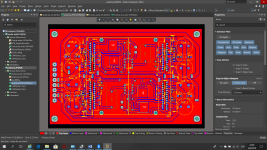
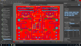
Could be the way you have mixed the power, input and output ground traces. Probably would have been better to have used a ground plane. As an example look at the return paths of the voltage regulators from the capacitors and the DRV.
Hey! I mounted my LM4780 the same way!
Hi.
I mounted my LM4780 in the same way. It works great.
However, it is wise to ensure you insulate the IC and screws (heatshrunk the unmated threads, and/or insulated washer under the head of the screw.
Verify isolation of each chip from the heatsink metal.
Although I suspect you would have more issue if there was a bug problem.
How is the signal routed from the input? Is there a preamp ahead of the amp? Or just the source? If all connections are twisted pair, I'd be tempted to remove or lift one ground wire at the input connection to check for source to amp ground loops
Last edited:
The schematic *seems* to show 20K and 47K NFB resistors, gain of less than 2.
Am I reading that wrong?
Hi! Yes it's correct. It's a schematic error, the PCB has the reference values from the parallel implementation in the datasheet
Could be the way you have mixed the power, input and output ground traces. Probably would have been better to have used a ground plane. As an example look at the return paths of the voltage regulators from the capacitors and the DRV.
Hi, I could solder the ground to the general (currently isolated) plane from the board. Should I do it?
Hi.
I mounted my LM4780 in the same way. It works great.
However, it is wise to ensure you insulate the IC and screws (heatshrunk the unmated threads, and/or insulated washer under the head of the screw.
Verify isolation of each chip from the heatsink metal.
Although I suspect you would have more issue if there was a bug problem.
How is the signal routed from the input? Is there a preamp ahead of the amp? Or just the source? If all connections are twisted pair, I'd be tempted to remove or lift one ground wire at the input connection to check for source to amp ground loops
Hi! I checked the isolation, it's ok. Although I only used thermal paste.
The signal goes directly to each DRV134, there is no preamp. The wires used are twisted pair, if I remove the signal from one channel I still get some output if the other channel remains connected 😕
Hi again.
If memory serves me correctly, each IC should be isolated, even if the heatsink is floating and ungrounded (the metal tab is connected to one of the rails IIRC, and may provide a route for supply current which is not desired, rather than supply via tracks on PCB and their local decoupling caps.
Is the noise measurable on a AC voltmeter?
Regarding grounding and input to the board, IF there is a common ground input between L and R channels on your board, AND a common ground star point within the output of your source, I.e. CD player, then you may set up a earth loop. I have run into the issue on commercial not DIY gear where I had to disconnect the ground wire in on channel on the connecting RCA cable to remove the loop.
Or...depending on source, especially mobile device, laptop etc the noise may be originating from the charger. I habe found this when sampling sounds from android devices. Unplugging the charger removes the noise.
I have found some sound cards cause issues too, especially if like me, you use loopback within the soundcard for recording of sounds and the monitoring loop.
If none of these apply, then perhaps the input to your board requires a rethink of the layout or DC blocking LPF and RF attenuating LPF needs attention.
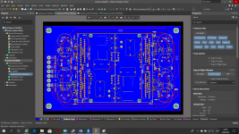
Here is how you could structure the grounds. Light green is the input and feedback returns. Power and the Zobel returns are kept out of the signal returns.
Don't use long traces to make the connections. Position the parts so that the returns are close together and then use a ground plane to keep the impedance low.
Don't use long traces to make the connections. Position the parts so that the returns are close together and then use a ground plane to keep the impedance low.
Attachments
Last edited:
Hi again.
If memory serves me correctly, each IC should be isolated, even if the heatsink is floating and ungrounded (the metal tab is connected to one of the rails IIRC, and may provide a route for supply current which is not desired, rather than supply via tracks on PCB and their local decoupling caps.
Is the noise measurable on a AC voltmeter?
Regarding grounding and input to the board, IF there is a common ground input between L and R channels on your board, AND a common ground star point within the output of your source, I.e. CD player, then you may set up a earth loop. I have run into the issue on commercial not DIY gear where I had to disconnect the ground wire in on channel on the connecting RCA cable to remove the loop.
Or...depending on source, especially mobile device, laptop etc the noise may be originating from the charger. I habe found this when sampling sounds from android devices. Unplugging the charger removes the noise.
I have found some sound cards cause issues too, especially if like me, you use loopback within the soundcard for recording of sounds and the monitoring loop.
If none of these apply, then perhaps the input to your board requires a rethink of the layout or DC blocking LPF and RF attenuating LPF needs attention.
Hi again, it turned out to be a faulty connection of the output (my bad, it was really late at the time). Also I did use the remaining plane as ground. The result is a huge improvement in the hiss, it's barely audible now. 😀
I tested these amp with a pair of klipsch rb-61 and it was awesome ii 😎
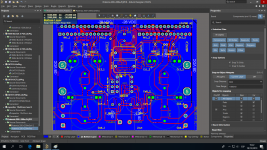
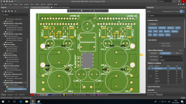
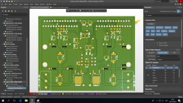
so..i've got some news afer all this time. Although the first board vertion worked pretty well i decided to take your routing advises and make mono channel board prototypes. Here are the results. Please let me know what you all think about it. Cheers! 😀
Attachments

- Home
- Amplifiers
- Chip Amps
- dual BPA200 based on LM4780 & DRV134