Seriously, find the thermistor and check it. Your symptoms are exactly like all the amps I have bought and fixed with that issue.
Ok Bob, will give it a go. If bad, could this just be what is keeping it from functioning?
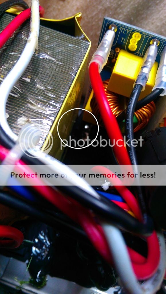
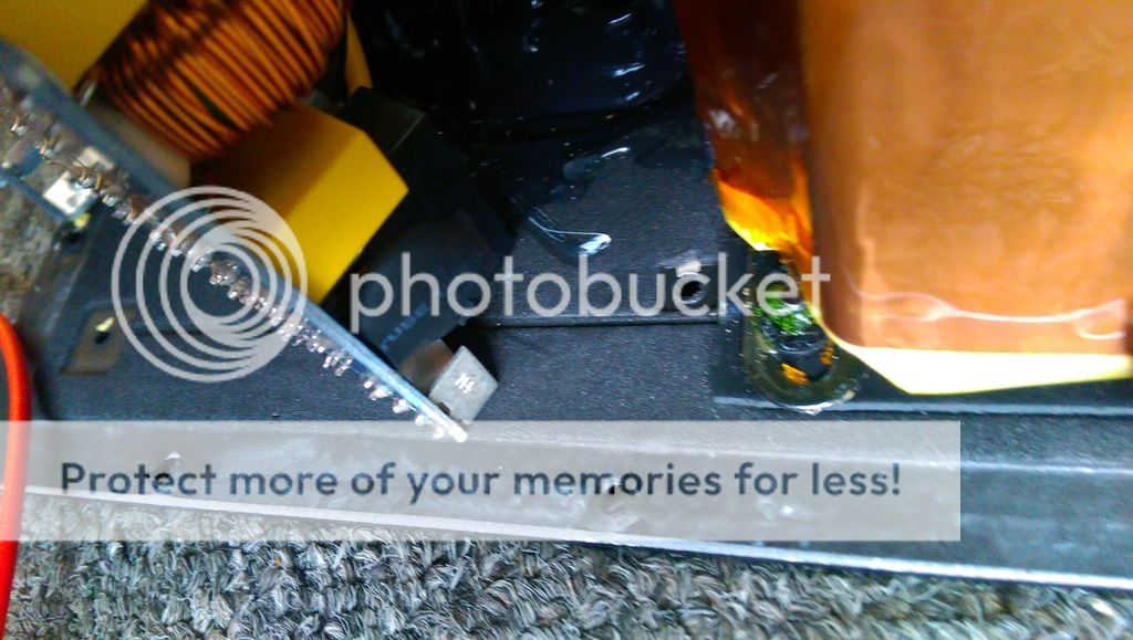
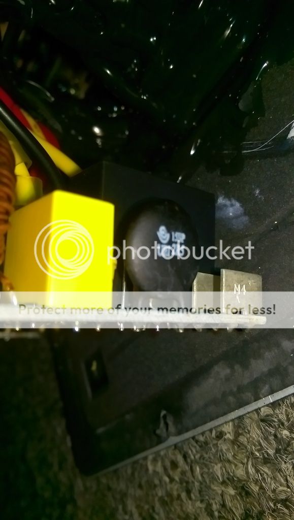
Done it, found the thermistor, so, going by a few youtube videos, set my multimeter to 20k Ohms and tested it, reading was 2 every so slightly different one's: 0.00 and 0.01, so I take it - it is faulty?
Yes, that is the thermistor.
I can't remember what the resistance was supposed to be, I think it varies based on the model. Basically, the thermistor is your circuit protection. About 5 dollars for a new one, vs replacing the whole system.
If you blow the thermistor, you can still get power on, but the current is unsteady/very weak/gone completely. This would explain a power light indicating power on, but very little/no sound +noise under load, as well as a dimming light.
If you take the heat shrink off the thermistor, be careful and do not shock yourself. These amps, in general, are very dangerous to open up (imo more than normal). If the thermistor is corroded and damaged, time to replace it.
Ok Bob I'll give it a go.
Can't I just drain the large power caps to possibly stop any shock?
I seen how to do it online, did it on a few things before, is it safe? Ie: just a bit of mettal going to each terminal underneath.
Can't I just drain the large power caps to possibly stop any shock?
I seen how to do it online, did it on a few things before, is it safe? Ie: just a bit of mettal going to each terminal underneath.
By the way, not sure as it's "in circuit" but, I did a continuity test on it also and it made the long test tone.
Looks ok, it's not perfectly rounded at the top, has a lil ridge, but those test results, hmm...
I'll take it out of circuit and test again as surely with 0.01 resistance values it must be faulty thus not sending enough power etc etc 🙂
Hi XsamuraiX,
Never, ever discharge capacitors by shorting them. You can damage a perfectly good capacitor, give yourself a shock, or cut yourself when your hands jerk back when the big snap is heard. Those capacitors are best discharged with a resistance. Below 100 VDC you can use your dummy load (8 R, 250W), above that you need much higher resistance.
A good value to use would be one that drains the filter capacitor over 20 seconds or so. You do not want a sudden discharge, longer discharge times are okay provided you wait until the capacitors are discharged. Use your voltmeter to be absolutely sure.
That thermistor appears to be fine. But, you never know, so take it out and test it. The information is sometimes printed on the body of the part.
-Chris
Hi Anatech, so a resistor that is around 5ohms? I see many using them types to discharge caps...
Hi XsamuraiX,
That's a little low, but it beats the heck out of a direct short. Can you use two in series?
-Chris
That's a little low, but it beats the heck out of a direct short. Can you use two in series?
-Chris
I bought a 10 ohm type so that should be fine 🙂 as soon as it arrives I'll discharge all the power board caps and post the results from the thermistor back here, hopefully it's the cause of my problems.
I had my sunfire sub repaired twice because it developed a low level hum. Each time, it was the capacitors on the board that were replaced as well as potentiometers. After it developed the hum for the third time I sold it for parts. I’d bypass the amp entirely and use an external amp. Sunfire subs and humming are very common. Good luck
I was able to fix the sub by replacing all the caps on the power board. Had to spend money on soldering iron, capacitor tester and caps. No more humming. That was fun...
Hi CVSaudio,
You had to buy a soldering iron, or was it a soldering station? Are you a service shop or servicing dealer?
-Chris
You had to buy a soldering iron, or was it a soldering station? Are you a service shop or servicing dealer?
-Chris
XsamuraiX,
I assume you've already done the easy stuff like swapping signal sources & RCA interconnects?
Bob Carver sold off Carver Audio decades ago, although I do believe he did contract engineering for them many years afterword. So awesome customer service is probable not to be expected.
I'll start of with a safety precaution: Your AC mains Voltage (United Kingdom?) is 230VAC! The Sunfire subs utilize a switch-mode power supply which first converts the 230VAC in to 345VDC which is absolutely lethal - no joke!
The previous suggestion of checking the in-rush current limiter is a good start.
It should be located right after the fuses, typically a dark colored two-lead disc shaped component. They typically get chalky looking with age, and tend to cook the solder joints too. Before checking anything, unplug the sub from the AC mains for an hour or two to fully discharged.
Next verify the Thermistor (current limiter) with the Ohms setting on a DMM, should read in the 10's of Ohms. If higher, or open circuit - well there you go.
If your feeling brave, using a DMM multi-meter you could verify the power supply output rails. A google search will tell you expected values. If still good, next step would be to trace an active input signal through the amp stage. This should only be done with a large dummy-load on the output of the amp stage, and an oscilloscope.
I'm going on a hunch here, but I'm betting PCBA diagnostics is not you forte?
If so, I'd go to the Carver Audio Forum or search Ebay for tested good pull out boards.
If your crafty you could remove the remaining good unit's electrical goodies and sell them. Then plate up the missing amp holes, install binding posts/Speakon connector and power up the pair with a high power DSP enabled PA amplifier. You'll need the Hi/Lo pass filters and especially the variable "Q" parametric EQ.
Of course the easiest route would be total replacement.
Good luck.
Last edited:
- Home
- Loudspeakers
- Subwoofers
- Anyone know a fix for a Sunfire sub?