Hi Tom,
From the ACA 1.6 we're moving to the Tensility 54-00064 for the DC jack. It's a bit more robust. I'll have one of those sent you you, please look out for an email from the store helpdesk.
From the ACA 1.6 we're moving to the Tensility 54-00064 for the DC jack. It's a bit more robust. I'll have one of those sent you you, please look out for an email from the store helpdesk.
As that has different number of solder terminals, I guess you'll need to update the build guides again
An externally hosted image should be here but it was not working when we last tested it.
Hello friends!
I have been modeling the AMP in LTSpice to try to better grasp the different functions of each part or section. I am a complete newbie, so please treat me as such. Maybe this is obvious for most of you, not for me.
I have trouble wrapping my mind around an issue: + OUT is mostly ground, and, as such, I am not even able to hook the 'virtual' multimeter to it, no matter how I model the scenario. Its ground, it has 0V. is this more or less correct?.
The - OUT as expected, has all the amplified voltage.
The scenario of the bridged RCA mono amp suggests "connecting the output of the + OUT to the input of the other channel". How is that output able to channel any voltage to the new input? When I model this, I do get an inverted signal going into the second channel, but it is a much lesser signal than the input fed to the first channel.
No matter what resistor I use there, the input signal to the second channel is about 1/3 of the original input signal and, therefore, the amplification of the 'bridged' amp results in a much lower Ch2 amplification.
What am I not seeing? What output is actually going through the grounded + OUT in the bottom of the schematic? Why am I unable to get voltage readings (all this theoretical, mind that I haven't yet build the amp!) at that position?
Thanks so much for any enlightening explanation.
Best regards,
Rafa.
The speaker posts are named + and - so that you connect the speaker’s terminals to them as intended by the designer, red to red, black to black.
This is done because the amplifier inverts phase, and to keep absolute phase, the speakers need to be hooked up “backwards”.
As you’ve noticed, the - output is actually the output of the amplifier circuit. It merely is named in reverse. 😀
This is done because the amplifier inverts phase, and to keep absolute phase, the speakers need to be hooked up “backwards”.
As you’ve noticed, the - output is actually the output of the amplifier circuit. It merely is named in reverse. 😀
Given that the software (CDs/LPs) have no standard for absolute phase, you still need to be able to switch the phase depending on which way the album (or song) is recorded, so the importance of a DUT having non-inverting phas eis not all that important.
I have Toyed with the idea of swapping the speaker terminals around to reflect what the amp is really doing.
dave
I have Toyed with the idea of swapping the speaker terminals around to reflect what the amp is really doing.
dave
Well, what color do you call chartreuse ? Just curious ... green , yellow ?
It might be me, but chartreuse makes me think of this:
Chartreuse (liqueur - Wikipedia)
😀
PS: I can confirm chartreuse enhancing the listening experience to some extend...
It might be me, but chartreuse makes me think of this:
Chartreuse (liqueur - Wikipedia)
😀
PS: I can confirm chartreuse enhancing the listening experience to some extend...
The speaker posts are named + and - so that you connect the speaker’s terminals to them as intended by the designer, red to red, black to black.
This is done because the amplifier inverts phase, and to keep absolute phase, the speakers need to be hooked up “backwards”.
As you’ve noticed, the - output is actually the output of the amplifier circuit. It merely is named in reverse. 😀
Thanks! Yes, that much I had figured out, sorry for explaining myself so poorly.
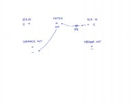
My question is, if this is the bridged mono amplifier:

What is actually fed to the second channel? How is that grounded / chassis +OUT able to put ANY voltage into the second channel? (for the Bridged version).
Thanks again, sorry for not even knowing how to word the question 🙂
Best regards,
Rafa.
This build guide says to set the 24v operating point at 10v. Am I missing something? I know it is not a critical setting, but 2 volts is a fairly large percentage of the value...
Where did you see that? I thought it was clear that 10 V for the 19 V PS and 12 V for the 24 V PS.
What is actually fed to the second channel? How is that grounded / chassis +OUT able to put ANY voltage into the second channel? (for the Bridged version).
I hope 6L6 will clarify this soon, my guess is that you need to invert the signal going in the other channel's input and that's why it's connected as shown.
Last edited:
didn't follow too closely but I believe what is used is an old trick , when having amplifier flipping phase on its output vs. input signal
ya want bridged , feeding it with SE signal ?
just toss output of driven channel to input of "free" channel , attenuated exactly with same values of resistors as you have for NFB chain
then connect load between two hots and that's it
ya want bridged , feeding it with SE signal ?
just toss output of driven channel to input of "free" channel , attenuated exactly with same values of resistors as you have for NFB chain
then connect load between two hots and that's it
What is actually fed to the second channel? How is that grounded / chassis +OUT able to put ANY voltage into the second channel? (for the Bridged version).
I hope 6L6 will clarify this soon ...
Good catch. I completely messed up the photos. (and will delete them in the time-being until I can make them new.) I too got caught up and tricked in the Red/Black=backwards thing. 😕 😱 Whoops!
As you have correctly analyzed, the signal to sent to the other channel must come from the output of the first, which is the black speaker post.
Which means the wire of the RCA plug with the resistor must be attached to the black post of the opposite channel, not the red.
... I believe what is used is an old trick , when having amplifier flipping phase on its output vs. input signal
...just toss output of driven channel to input of "free" channel , attenuated exactly with same values of resistors as you have for NFB chain
then connect load between two hots and that's it
Exactly what is going on here.
Where did you see that? I thought it was clear that 10 V for the 19 V PS and 12 V for the 24 V PS.
That is correct. Set bias at roughly 1/2 the PSU voltage.
Mono block switch operation
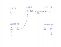
In my build of the ACA I have the front mount power switch that leaves the rear mount power switch unused. I thought it might be interesting to use the unused switch to change from stereo to mono block operation instead of using the external jumpers shown in the build guide. Will the hard wiring schematic I've included here work for that purpose? I believe the schematic accounts for the inversion of polarity, correct?
In my build of the ACA I have the front mount power switch that leaves the rear mount power switch unused. I thought it might be interesting to use the unused switch to change from stereo to mono block operation instead of using the external jumpers shown in the build guide. Will the hard wiring schematic I've included here work for that purpose? I believe the schematic accounts for the inversion of polarity, correct?
Attachments
I was waiting for the big guns to chip in, but since there has been no reply, I may as well jump in.
I have very little knowledge, but since there is this confusion regarding out + and out -, I'll say this: remember that each channel is phase inverting. So, yes, you should put the wire to the out -, but keep in mind that this has already been dealt with reversing the polarity of the speaker binding posts. So, just that there is no confusion: the wire should go to RED terminal. So, yes, it is the real out - of the amp, but it is the one that is connected to the speaker + input.
Also, for the sake of 'correctness', the channel out feeds the RCA in of the other channel, so the arrow should really point the other way around (not that it matters, obviously, but just to be sure the concept is correct!).
Best regards,
Rafa.
Got it. Does it matter if the resistor goes between the binding post and the switch or the switch and the RCA?
... but since there is this confusion regarding out + and out -, I'll say this: remember that each channel is phase inverting. So, yes, you should put the wire to the out -, but keep in mind that this has already been dealt with reversing the polarity of the speaker binding posts. So, just that there is no confusion: the wire should go to RED terminal. ...
No, because the red post is electrically ground.
The small wire with the 39K resistor in series connects the speaker output of the first channel to the input of the second channel. Which means the BLACK post to the center of the other channel RCA.
Freejazz00, your drawing is correct if your red posts are inboard and connected to the ground buss.
(Of note, Rafa's mention of the arrows pointing the other way is the correct concept. 😀 )
... but since there is this confusion regarding out + and out -,
Yes, there is lots of confusion regarding the speaker post polarity and because of it I might make the speaker posts the other way in the next guide... We'll see...
... Does it matter if the resistor goes between the binding post and the switch or the switch and the RCA?
Resistor location makes no difference. As long as the circuit is complete, series is series. 🙂
Last edited:
Yes, yes, yes!!! Sorry, the black post, yes. I myself pointed out earlier that the red post is ground, and now I go and suggest that connectionNo, because the red post is electrically ground...

Don't feel bad. The confusion is common, myself and others have been tricked by it already!
Last edited:
geeze, and you build these things for a living. 🙄
I was almost thinking of installing the black speaker posts on the inside, and making a little label stating "Note - this amp inverts absolute phase "
When Dave finally gets around to using his pair in bridged mode, it'll be on the balanced input, so this little confusion will be moot.
Totally separate question - any particular reason the ACA1.0 couldn't be run in bridged mode? Dave has a pair of the original mono-blocks, as well as a pair of the new stereo unit. Even if kept in the original separate chassis, it wouldn't take much to fabricate a new top & bottom cover to unify them for handling, and presumably they could both be run off either one of the new 24V SMPS, or something equivalent - with bias adjustment, of course.
For posterity I've corrected the picture based on 6L6's comments (many thanks).
I believe that others have pointed out that image 48 of the build guide is in error. I believe this should be shown as the RCA jumper on the left should be connected to the black speaker post on the right. Also, I believe that right speaker output wire should be in the left (red) post.
I believe that others have pointed out that image 48 of the build guide is in error. I believe this should be shown as the RCA jumper on the left should be connected to the black speaker post on the right. Also, I believe that right speaker output wire should be in the left (red) post.
Attachments
- Status
- Not open for further replies.
- Home
- Amplifiers
- Pass Labs
- ACA V1.5 Illustrated Build Guide