
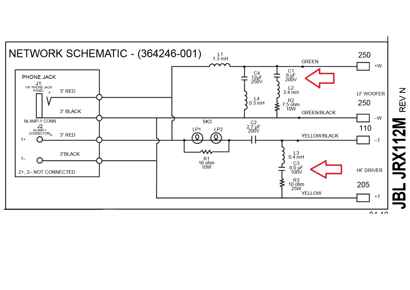
Question is if these capacitors are part of the zobel or if these capacitors are part of the crossover circuit ...
These tend to short or leak easier than expected so i wonder what will be the difference if i skip them any way
These tend to short or leak easier than expected so i wonder what will be the difference if i skip them any way
The 8uF ( in the HF leg ) forms part of a low-Q, 2800hz notch.
The 8uF ( found in the LF leg ) is part of a high-Q, 965hz notch.
I wouldn't disable these notchs since they actually are shaping the overall response.
If they are blowing up it's because the voltage rating must be under-speced for the sort of duty you're putting them through.
Replace these ( BiPolars ) with Mylar film ( or Polypropylene ) capacitors rated for 400V.
🙂
Question is if these capacitors are part of the zobel or if these capacitors are part of the crossover circuit ...
They are not Zobels. They are LCR (conjugate networks). Their purpose is to damp the resonant peaks of the drivers.
Do not remove them. It affects the sound.
As Earl suggested, change them to Polypropylene 400V. They last forever.
Michael ...good to see you after such a long time !!! Hope you are doing fine
Earlk thanks for the detailed explanations
Correct the quality of parts there creates problems most of the time cross point choice there is a bit overestimated next to the driver and teh sound of those was never something realy nice
One way or another the circuit is now changed in the 212 series and cross point is altered any way
Thanks for your help my friends !
- Status
- Not open for further replies.