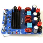
this one with the heatsinks was only $7 more expensive (after coupon) than the one without, I went with the cooler looking one
The heatsinks definitely make it cooler! 😎
Putting the 3255 in a case will hide it’s green LED. I’m thinking about relocating it to the front panel or leaving it alone and adding a new LED to the front panel. Any suggestions or warnings?
Got it from one of the sellers in Taobao. It was sold for $40 but the bummer was shipping cost at $37 which is fair enough for an item 12in D X 17in W X 4in H and weighing 6kgs 😀Where did you pick up that enclosure?
😀😀😀 it does indeed 😀😀😀The heatsinks definitely make it cooler! 😎
Attachments

Putting the 3255 in a case will hide it’s green LED. I’m thinking about relocating it to the front panel or leaving it alone and adding a new LED to the front panel. Any suggestions or warnings?
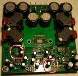
I would put the diode with the resistor to the power connectors. If an error occurs, you must open the box and check the FAULT and CLIP_OTW LEDs. Reason of fault is in table on datasheet. I think signal for FAULT and CLIP_OTW LEDs can use when you solder your LED with hole on board and Ground. They are located below Heat Sink. Please be careful, and first measure it!
Attachments
Can anybody give me a description how to implement PFFB - in easy/simple terms (best would be step by step guide) a not very well-informed member might grasp? Thx in advance.
Putting the 3255 in a case will hide it’s green LED. I’m thinking about relocating it to the front panel or leaving it alone and adding a new LED to the front panel. Any suggestions or warnings?
You can place a 3 V LED across the # 4 (gnd) and # 8 hole (3.3 V supply) of the 28 hole double row interface socket (check the schematic on p 17).
Regards,

Can anybody give me a description how to implement PFFB - in easy/simple terms (best would be step by step guide) a not very well-informed member might grasp? Thx in advance.
A Google search with "pffb tpa3255" gives you the TI document that describes what you need to do.
Thanks for the helpful suggestion - found the document in question, but I still have a question or two. I found those empty solder pads for most components needed to implemet PFFB but what about those parts which don't seem to have such a fixed spot (namely C_fb_in and _out and R_fb_gnd)? This is all pretty small below the board so I am a bit at a loss here. Any support will be greatly appreciated - thx in advance.
You can place a 3 V LED across the # 4 (gnd) and # 8 hole (3.3 V supply) of the 28 hole double row interface socket (check the schematic on p 17).
Regards,
Thanks. I’ll look into it and report back.
fault and clip leds
Hi,
Thanks to everyone here who inspired me to order a 3255EVM board, so far it sounds very good on the bench.
I am clear about how to wire up an external suspend/mute switch, and how to wire a power indicator led. I have a question about exporting some more functions of the J28 interface connector to an external panel.
If it's simple to do, I would also like to export the FAULT and CLIP_OTW active low pins to 2 more external leds. On the EVM board the 2 on board leds are driven from mosfets, the 12v and 3.3v rails and a bunch of resistors.
The clip and fault lines have internal pull-ups to 3.3v, apparently to reduce external component count - I don't know what that means or how many components are needed. I don't want to solder or desolder the EVM board directly.
I am wondering if there is a simpler circuit than the one implemented on the EVM. I wouldn't mind if the leds switched on, or switched off, to indicate fault conditions. My case has an auxiliary 12v supply available if it's any use.
I apologise that while I have some theoretical background in electronics I have a lot to learn, because I never got any practical experience until recently.
So if I can get away with (say) a simple resistor and led circuit it would be worth exporting these signals, but if it's going to involve transistors or a custom PCB I won't bother, I'll just have to squint inside the case.
Thanks.
I too am interested in responses to the questions of Ytheleus above, but I’m also prepared to squint.
one method to bring the LED's out to the case would be a light pipe, i.e. small diameter acrylic or glass rod. Place it directly above the PCB mounted LED and route it to a viewing hole in the enclosure. No need to solder or add LED's, though affixing the light pipe brings about it's own issues.
- Home
- Amplifiers
- Class D
- TI TPA3255EVM