Linear circuit design was a lost art in 1985? Seems people keep finding it an arguing about it to this day. Just like Swift foretold in 1728!
Maybe in the eyes of the audio community, or should I say The Hermetic Order of Audio Craft.
Last edited:
🙂
Tonight I am killing a valve preamp to replace its guts with many many 8 legs and switched mode supplies and reed relays. Any more heresies I should add?
Tonight I am killing a valve preamp to replace its guts with many many 8 legs and switched mode supplies and reed relays. Any more heresies I should add?
Look everybody, this has always been a controversial thread. I like it that way, so I have kept going for the last 12 years or so, putting up with insults, moderation, and general impugning of my designer's reputation, but I still slog on, because new ideas are wonderful, stimulating and can be fun to work with.
Hi John, I kinda gathered that - the irony is that being even slightly controversial is being frowned upon and I am hardly an audio rebel and yet treated as if. Just inching past what they deem acceptable has to be 'shut down' (and I am quoting you here) or should that be 'shouted down' - if only we were allowed to be slightly controversial, it would actually make the thread better. We might also get some fresh blood when it comes to participants. Every great river needs a flush every now and then.
But free speech is only deserved by those who claim it, even if there is a price to pay!
Being controversial is fine. Spouting gobbledygook will get peanuts thrown. Has always been the way. You do keep quoting this 'shut down' as if that is your goal with every thread you start.
There is an emerging hypothesis that current stability is important for the correct function of a conventional Class A-B amplifier as well as for the speaker itself. We know with certainty that aberrations of almost any kind, from poor driver design and many more factors, can modulate the impedance of a speaker, which in turn can modulate the amplifier current - the very thing that the amplifier has no direct control. The base impedance is the DC resistance of the driver and is stable - can we all agree on that? So any added impedance above the Re is not so stable, because here we observe changes that shoves around the current - the word corrupting the current comes to mind. Finally, a current is presented to Re of the driver and that forms an internal voltage, the current here and the voltage formed there determines the final dB-SPL of the driver. This is not only possible to prove with modeling, but also in physical tests. If the current is reduced (and this current has no direct control by the amplifier) to half, the voltage will also be half and the output of the driver will be reduced by exactly 6dB. But the stability of current that formed that new dB-SPL is at the mercy of the less than stable impedance above the Re value of the voice coil.
Why does the voltage change? You said the voltage is directly controlled by the amplifier, the speaker impedance changes, so the current through the load changes. I think we can all agree with that, but why does the voltage also change? I thought the whole idea was that the amplifier is a voltage source and the current varies iinversely as the load impedance varies (both above and below Re). Where are you deriving the voltage change? You make it sound like the current has spontaneously changed through a fixed load impedance, which changes the voltage, which you said was constant but the impedance changed. I am obviously missing something in that paragraph, and would really appreciate some clarification.
That's confusing. Joe R's "Elsinore" speaker is described as "current compatible". What does this mean? In combination with his link to his transconductance amplifier project I took this to mean the Elsinore is meant to be driven by a transconductance amplifier. But on further reading of the website I can find no such indication and in this thread Joe denies (repeatedly) promoting current drive while at the same time saying current drive is superior due to variable driver impedance. Curiouser and curiouser.
What the heck is Joe going on about? I'm not sure why I care. I suppose I don't normally think about speaker design so this is new. If anyone thinks they know and can be bothered to put it in a nutshell for me I would be obliged.
This is too silly to answer in detail - so I will only give one comprehensive answer:
The Elsinores can be driven by any amplifier of any output impedance, the alignment stays in place (other than a minor blip just under 20 Hertz) and also the crossovers are locked into place and this is what explained by just one thing - the amplifier sees a load so that the current is the same at all frequencies - this is the essense of current EQ, the current is equalised to be the same (or as close as can be) at all frequencies.
No mention of current drive, here or elsewhere, as being my preferred amplifier - and an intelligent person should be able to grasp that, OK?
Constant current (load) is not the same as constant current drive (amplifier)!
Hi Joe,
Just so I understand you correctly, you're saying that you could basically take a high current amplifier, like a Krell for example, and insert some reasonable values of resistance in series with the speaker and the response wouldn't change? By reasonable values of resistance, I mean that the sound level can be maintained without any trouble by increasing the drive voltage from the amplifier without getting into clipping.
So you are basically saying that your speaker design presents as a resistive load at all frequencies in the audio spectrum.
-Chris
There is an emerging hypothesis that current stability is important for the correct function of a conventional Class A-B amplifier
Only in the minds of a few, again a feel good hypothesis with no real substance. Joe is irritated that folks are not flocking to his speaker solution.
Last edited:
Go to #3778 and look at the amp mod and the resulting speaker's acoustic output THD reduction.
Tell me why this happens... reduction in THD from the loudspeaker.
First one with the correct answere wins the Grand prize. OK Waly is included.
THx-RNMarsh
Tell me why this happens... reduction in THD from the loudspeaker.
First one with the correct answere wins the Grand prize. OK Waly is included.
THx-RNMarsh
Last edited:
Why does the voltage change... I am obviously missing something in that paragraph, and would really appreciate some clarification.
That's fair enough, and the answer is surprisingly simple - but it takes a little effort to realise how that is the case.
I have a Peerless Nomex driver, it has a DC resistance of 6 Ohm, the Re of the driver. At around 1500Hz the total impedance has doubled to 12 Ohm. If we were driving this from an amplifier with 6V RMS output, the load will draw 500mA. If there had been no additional inductive back-EMF, then the current would have been a full 1 Amp. We have reduced the current by half.
Now the Re will see 3V and the back-EMF part of the impedance also 3V, we have a split because the two are in series.
It should be apparent that a high source impedance equals current drive, so let us use that as a reference - and now our driver would now see 12V across its terminals. Just follow what the current does. Now the back-EMF will see 6V and the Re the other 6V, being in series, the driver terminals will see the full 12V.
But the back-EMF contributes nothing to the dB-SPL of the driver, it is the voltage across Re that does. But even more, and this applies with both current and voltage drive, since the presence of back-EMF impedance, the voltage across the Peerless driver will never be the same as that which can be calculated as arriving at Re, which actually produces the dB-SPL (you will need to put a microphone in front of the speaker with a baffle). In the presence of additional series impedance, that voltage will always be lower, lower than what the terminals sees.
In our voltage example above, 500mA versus 1 amp, the dB-SPL will change by 6dB, but the back-EMF does not contribut to the dB-SPL at Re where the current times voltage (and the voltage is formed by the current) affects the force that produces dB-SPL.
The back-EMF is basically a series impedance (being back-EMF it is in itself a voltage source that impedes (and hence an impedance) the current.
That back-EMF causes current that is less than stable and all those funny wrinkles that show up in the impedance plot, that should not be there, affects and changes the back-EMF impedance - the Re is rock steady (but of course it has thermal dependency issues, so there is no free lunch).
Perhaps the below attachment should help. Cheers, Joe.
PS: I added the last double graph to show that it works at all frequencies, even at 42 Hertz and the motional impedance (which is also motional back-EMF). Hope you find it interesting.
Attachments
Last edited:
Richard, I am pretty sure that your circuit change adds a small amount of positive current feedback that tends to partially cancel the RESISTANCE (what is measured with a DC driven ohmmeter) that limits the damping of the bass driver at resonance. This should reduce the peak excursion of the driver and therefore lowers the distortion at the fundamental resonance. I think that it is called 'negative damping factor'. This technique is also used by Audio Precision in its oscillators, and it is a very powerful tool that most here have probably never heard of.
Last edited:
Overhung by definition has front coil which does not couple to the flux return, so will have variation. Underhung reduces flux return as it moves forward.
Jn
First post on a cell phone. Pita
I thought I was overhung, but have been informed I am underhung. No coupling, no flux. Now I'm just hungover.
I think that it is called 'negative damping factor'. This technique is also used by Audio Precision in its oscillators, and it is a very powerful tool that most here have probably never heard of.
John between you and me I don't think Joe is going to further your cause.
🙂
Tonight I am killing a valve preamp to replace its guts with many many 8 legs and switched mode supplies and reed relays. Any more heresies I should add?
I could use the valves if you have no use for them 🙂
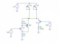
After reading the Bob Katz article that was recently posted, I decided I need a preamp with a strong 2nd harmonic character. Let´s say 0.3% to 0.4% THD. I have to look up the formula and see what the corresponding level in dB is.
The one shown below has a gain of 36 times. My usual sources are multibit DACs with a small resistor for current to voltage conversion. With an input of 50mV peak the output is 1.8V peak, and the 2nd harmonic is -60dB down. 3rd harmonic is -85dB down.
Folded cascode is nice, doesn´t require much supply voltage and the PSRR is good. Bandwidth should be good because of the cascoding.
Using a PNP for the cascode looks much worse. I hope the 20 or so 2SJ74 I´ve got are genuine, I believe they are. I bought them many years ago here at diyaudio.
Wish me luck 🙂
-Alex
Attachments
Last edited:
Well I hadn’t looked at Joe’s site. I am impressed.
Joe, you have put a lot of work in there. Congratulations!
Wow! Thanks George, much appreciated. Joe
- Status
- Not open for further replies.
- Home
- Member Areas
- The Lounge
- John Curl's Blowtorch preamplifier part III