JBL T-Amp From 1966 - Anyone Build it or something similar?
I first heard about this amp when, Bob Cordell and andy_c brought it up, mentioning that it had an output stage triple. I never bothered to look into it until last year and have been wondering why the RCA reference design and derivatives get so much attention and builds and this one nearly no discussion.
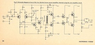
I don't know if I'll ever build something similar, but here is an article by Bart Locanthi from January 1967 in Electronics World: https://www.updatemydynaco.com/HistoricDocuments/JBLTAmp.pdf
The JBL integrated amp models SA-600 and SA-660 incorporate this power amp.
Sevice manuals for this amp can be found here: JBL SA600 - Manual - Solid State Amplifier - HiFi Engine
Interesting features are higher voltage supply rails for drivers and front end. Triple EF output stage, two stage diff pair front end, and inverting feedback configuration. Also, interesting that emitter degeneration and no Cdom compensation was used before they became popular. Output stage emitter resistors are connected in the way that is currently popluar. It is refreshingly simple, might want to add a cap bootstrap on the VAS or a current source.
I first heard about this amp when, Bob Cordell and andy_c brought it up, mentioning that it had an output stage triple. I never bothered to look into it until last year and have been wondering why the RCA reference design and derivatives get so much attention and builds and this one nearly no discussion.
I don't know if I'll ever build something similar, but here is an article by Bart Locanthi from January 1967 in Electronics World: https://www.updatemydynaco.com/HistoricDocuments/JBLTAmp.pdf
The JBL integrated amp models SA-600 and SA-660 incorporate this power amp.
Sevice manuals for this amp can be found here: JBL SA600 - Manual - Solid State Amplifier - HiFi Engine
Interesting features are higher voltage supply rails for drivers and front end. Triple EF output stage, two stage diff pair front end, and inverting feedback configuration. Also, interesting that emitter degeneration and no Cdom compensation was used before they became popular. Output stage emitter resistors are connected in the way that is currently popluar. It is refreshingly simple, might want to add a cap bootstrap on the VAS or a current source.
Attachments
Last edited:
...higher voltage supply rails for drivers and front end.
...might want to add a cap bootstrap on the VAS or a current source.
If you have higher driver rails, you don't need these tricks.
...wondering why the RCA reference design and derivatives get so much attention and builds and this one nearly no discussion.
Because, commercially, multiple rails at odd voltages and powers is just awkward. (Yes, DIY folks do more awkward things naturally....)
It does not seem to be any great advantage over any other 5-stage amplifier. (5 stages of current gain was a LOT in days of 3-stage amplifiers. Also 10 transistors was a lot in days of 6- or 7-transistor amps.)
The compensation seems appropriate. Pole-splitting cap around VAS might be fewer penny-parts but probably not different performance. (And with the push-pull here, maybe not fewer parts...)
With modern parts you could just run the whole thing on the highest rail and live with any loss in power due to not going rail to rail. I don't like the multiple rails. Gain in the output stage might be a better way.
Voltage swing is one consideration but a current source or bootstrap also provides more gain.
Darlington outputs simplifies this quite a bit.
Voltage swing is one consideration but a current source or bootstrap also provides more gain.
Darlington outputs simplifies this quite a bit.
Designed in the days when small signal transistors were $1 and TO3 transistors were $10? No wonder nobody built it. Way too many transistors.
Also three transformer windings (vcc 1,2,3) was weird, never saw such a transformer for sale. Two transformers would have been clunky and heavy. Besides silicon rectifiers (no bridges then) were about $.60 each. That would have been about $3.60 in rectifiers even if the Vcc windings had center taps. Companies were still installing selenium rectifiers then rather than bust their cost targets.
5 transistor/channel designs captured the market then, price leaders like Leak 70 & dynaco ST120. A lot of vacuum tubes were being sold too, much cheaper for 30W up until about 1972.
I'm talking about building it in the last 10 or 20 years, here on this forum. There are certainly ways around the multiple supply voltages.
- Status
- Not open for further replies.