Hi all,
Hope someone can assist debugging this problem. I am getting very low frequency noise (pumping) on my conrad johnson Premier 15 tube phono preamp. The noise frequency is below 1Hz. My Fluke DMM sees it as DC as the frequency is too low for it to measure this as AC. Switching on the subsonic gets rid of the noise at the outputs and the preamp is completely silent however this leads me to believe there is some problem with the preamp. Without the subsonic filter the pumping can get as high as +/-1.5v which given the high gain of the preamp makes sense. I have tried replacing tubes, playing with grounding to no real effect.
Any ideas?
Thanks, Ron
Do you have the cartridge connected to the preamp?
What is the preamp input, MC or MM?
What is the internal termination of the preamp input?
Is the turntable and cartridge located over any magnetic signals, such as a single ended power amp?
Schematic?
What is the preamp input, MC or MM?
What is the internal termination of the preamp input?
Is the turntable and cartridge located over any magnetic signals, such as a single ended power amp?
Schematic?
With a classical unregulated, filtered supply you can get subsonics due to mains voltage variations. 1.5 V is a lot, though.
The supply in the Premier 15 is regulated and I get these subsonic noise with no input connected on a test bench. Even if I short the inputs I am still having this problem. The input is MC through a transformer.
This issue is really puzzling me. Any help pointing me in the right direction will be appreciated.
This issue is really puzzling me. Any help pointing me in the right direction will be appreciated.
Can you measure the spectrum somehow? If you can determine a corner frequency and have the schematic, maybe you'll find a matching RC product somewhere.
For example, if the reference of the voltage regulator is filtered with a 160 ms time constant and that 1 Hz you mentioned is a corner frequency in the output noise spectrum, that would be a clue that it might be the reference.
For example, if the reference of the voltage regulator is filtered with a 160 ms time constant and that 1 Hz you mentioned is a corner frequency in the output noise spectrum, that would be a clue that it might be the reference.
I am getting very low frequency noise (pumping) on my conrad johnson Premier 15
tube phono preamp. The noise frequency is below 1Hz.
Usually this means the coupling capacitor after the first stage is too large,
unless there's a bad (or too small) decoupling capacitor in the power supply.
Usually this means the coupling capacitor after the first stage is too large,
unless there's a bad (or too small) decoupling capacitor in the power supply.
The power supply is regulated and well filtered but you gave me an idea with the interstage coupling cap. The original cj design uses 0.47uf. I have a similar 0.15uf cap that I can try.
The power supply is regulated and well filtered but you gave me an idea
with the interstage coupling cap. The original cj design uses 0.47uf.
I have a similar 0.15uf cap that I can try.
That has a good chance of improving the noise problem.
It may be necessary to change the capacitor in both channels
to eliminate the noise. Hopefully this LF noise was not in all
of these units.
Regulators can oscillate at LF, since they are feedback amplifiers.
Last edited:
For some reason I find this interesting. Dunno. So far, most of the advice (which clearly isn't bad advice!) is to change out components along the audio chain that allow infrasonic signal to pass relatively uninhibited. Rayma asserts that the 150 nF cap may well help in replacing the 470 nF. It raises the pole¹ by 3× in the frequency domain.
It might be nice to see an actual circuit diagram if you can lay hands on it.
______
One of those things you never read about much — because its largely anecdotal — is that the “body field” of people near highly sensitive high-impedance wiring can have substantial effects on things like infrasonic wow or signal drift. Just moving around a foot from an open back of an oscilloscope can cause it to drift all over the place. Well, back in the days of Tektronix tube scopes. You know, dinosaurs and all that.
So that observation begs, “does the ±0.7 V infrasonic signal happen when the amp's chassis is buttoned up?” Its a data point.
The other thing is, “is there no input 'cuz there's nothing connected?” The "yes" answer invites the follow-on, “is the preamp then amplifying whatever the unloaded leads are dragging in as antennae?” Kind of back to the first question, I guess.
Lastly, if as you claim, depressing the LF-CUT switch generally takes care of “the problem”, then it spurs one to consider that perhaps Conrad designed a 'pure' form to please the letter-of-the-design purists, … found the infrasonic single-digit volt drift … and proactively implemented the infrasonic CUT filter to address the real-world issues that it in turn caused. Could be. Conrad Johnson makes magnificent equipment, but they're practical enough to design both for purists and real-time, real-world needs.
Just asking.
GoatGuy
_______
¹ POLE - in signal processing and classical analog filter design, one refers to “poles & zeroes” for filters. For reasons that are fascinating but rather hopelessly long-winded, the poles in classical filter design are the characteristic frequency position where an order-of-filtering (attenuation, phase shift, or roll off) occurs. Can't go further into it without writing a treatise!
Last edited:
ronenash,
When you said you shorted the inputs, did you mean the phono plug inputs, or did you mean the input leads of the MC step up transformer?
Is the low frequency bump in both channels?
Do you have very low power line voltage?
That can cause regulated supplies to either drop out, or oscillate as the rest of the circuit drags more current when the voltage comes up, then drop out of regulation . . . and back in regulation . . .
I once had a Naval Officer who left the power voltage setting switch his solid state amplifier in the 220V position when he came to the US (110V to 120V power).
The amplifier actually worked, but not very well. You would just think it was a low power amp (which effectively was). Amazing how well it did work.
GoatGuy,
Filters . . . Reminds me of when I used the definitive "Filter Bible". It was written by Zverev, a Russian (not a Pole, pun intended), when he worked for Westinghouse.
I also once heard an over-simplified explanation of a low pass filter for those who do not understand filters very well:
"A low pass filter delays increasingly higher and higher frequencies, delaying them increasingly more and more, until the highest frequencies never come out".
Last edited:
"A low pass filter delays increasingly higher and higher frequencies, delaying them increasingly more and more, until the highest frequencies never come out".
LOL GoatGuy
I would assume the *original* values were not wrong, and would not start with ad-hoc changes. (Well, actually _I_ would....)
There have been "good" phono amps with sub-sonic troubles. The Dyna tends to bump in the decade below 1Hz, which is sadly close to the warp-rate of a 33RPM disc. If it outright howled 0.5Hz it would have been noticed! But it is only a bump, and far-far below the usual 20Hz test systems of the day.
I would re-re-check that power supply, because it can be the path for motorboating sneak-back.
I would replace the input tubes. A mere bump does not make signal. However a tube with rising 1/f random noise gives it more to bump-up. This is a somewhat common fault in otherwise excellent tubes.
As a practical man, phonos NEED subsonic filters. If the subsonic wobble is not "too big" (1V at output is marginal), then just filter it off and live happy.
Thank you everyone for your help. Rayma's post gave me an idea to check the regulators. God knows why I did not do this earlier. conrad johnson uses a two stage descrete regulation scheme and the transistors at the output of the first regulation stage were fried which caused the output of the first regulation stage to be at 230v vs. 360v. As a result the second regulation stages which should output 300v and 330v respectively could not regulate the voltage and were inducing noise into the system.
I should make a mental note to always check the supply voltages first. I guess I saw 230v and did not realize it not the spec'd output voltage.
Again, thank you for triggering my brain to think 🙂
I should make a mental note to always check the supply voltages first. I guess I saw 230v and did not realize it not the spec'd output voltage.
Again, thank you for triggering my brain to think 🙂
conrad johnson uses a two stage descrete regulation scheme and the transistors
at the output of the first regulation stage were fried
That's great, can you post the complete schematic?
. . . The most universal Very Low Frequency "Signal Source" that is across All of Line Powered Electronics is . . . 'Power Line Bounce'.
. . . The most universal Very Low Frequency "Signal Source" that is across All of Line Powered Electronics is . . . 'Power Line Bounce'.
Yep.
Its a powerful argument too for non-absolute regulation.
MOSFET pass regulation with a gate at 83% (1000 kΩ top + 4700 kΩ bottom) of VDRAIN, stabilized with a modest HV electrolytic cap (1.0 μF). Serves like a high-value inductor at squashing ripple, serves as a current-draw independent voltage regulator, serves as a powerline relative regulator too. And its "soft start" too… 50% in ½ second, 90% in 1.9 sec, 98% in 3.2 sec, 99.8% in 5 sec. There's another way… which is almost too complicated-to-talk-about, but you can use 5 sections of MΩ resistors and smallish caps to make a 5th order RC delay line; the rise at start is much slower. Its quite easy to model the rise of a tube-type rectifier in this way. Without a tube.
OF COURSE this puts “the weight” on the designer to competently design “the circuit” to deal with a wide range of line voltage variation. In the case of the OP's amp, nothing could be done until he found the knackered regulation transistor to begin with. No matter what you do, Murphy (entropy + odds) is going to bite whatever design you polish to perfection.
GoatGuy
That's great, can you post the complete schematic?
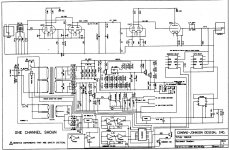
Here is the schematic. Still working on resolving this. Ordered the transistors in the regulator. Hope once they are replaced the problem will be solved.
Attachments
- Status
- Not open for further replies.
- Home
- Source & Line
- Analogue Source
- Hign subsonic noise in CJ Pr15 phono preamp with no input