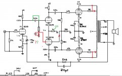
My learning-hack amplifier, an well worn Audio Innovations 800 need repair again. Faulty PCB due to heat. I have decided I want to implement some modifications while working on it. I hope fellow forum members can chime in with advise on feasibility of my planned modifications. Attached schematic show EL34 for outputs, these has been replaced by 6L6GC tubes.
My ideas are to implement and test in three phases:
1 - Triode wiring of 6L6 output tubes (indicated in red in attached schematic)
2 - Modify phase splitter from paraphase to LTP, making it similar to classic Mullard design (also red in schematic)
3 - If 1&2 goes well, DC couple input stage and implement CCS in splitter (in green). The later would also mean a rewiring and elevating the ECC82 heater supply (not shown)
My prime areas of concern are:
1 - Will my changes as drawn work?
2 - Will this have negative influence on stability?
3 - Can I remove the 100u decopling capasitor on the input stage? If so what will happen to frequency respons and stability.
4 - What kind of test should I perform for each stage of modification?
All feedback appreciated
Attachments
Have you modified the amp to dramatically reduce that 47K grid stopper on the 12AX7? Replace it with a 1K resistor while you're in there.
The 150K and 130K grid leak resistors on the output stage need to be the same value if you do what you're doing.
When you do a mod like this and you directly couple the second stage (good plan), you'll want to look at the power supply to see if there's some extra voltage available for the 12AU7. 12AX7s also do well with more voltage and a higher plate loading resistor.
Pay close attention to the heater/cathode insulation rating for all of your tubes. I don't think you'lll run into issues, but this can be a bit annoying to hunt down if you forget about it.
Removing the cathode decoupler will reduce loop gain, so improve loop stability at the expense of increased distortion because there will be less loop gain available to linearise the output stage.LJT said:3 - Can I remove the 100u decopling capasitor on the input stage? If so what will happen to frequency respons and stability.
A 12AU7/ECC82 LTP will be unbalanced without a CCS tail. That may be why the Mullard circuit uses a 12AX7/ECC83 LTP - this will work fine without a CCS.
I like the idea of your modified circuit.
As was stated in the thread, the filament to cathode voltage of the ECC82 will need to be addressed.
If you can, add a separate small center tapped 6.3V filament transformer, and tie the center tap to a resistive divider from B+ plus a bypass cap from the bottom divider resistor to ground.
That allows the voltage to be near to the cathode voltage, but without raising the filament DC voltages of the other tubes (the reason to use a separate 6.3V transformer). Be sure to locate the new 6.3V transformer so that its magnetic field, and its primary power wires do not interfere with the rest of the circuitry.
Make sure that the CCS for the ECC82 can take the maximum voltage of the quiescent cathode voltage, plus the largest signal voltage that will move the cathodes.
Do retain the input tube's cathode bypass capacitor across the 1k resistor.
You have reduced the gain of the output stage in two ways, the lower transconductance of the 6L6GC versus the EL34; and because of the change from Ultra Linear to Triode wired.
The triode wiring causes there to be a lower output impedance, with or without negative feedback, versus Ultra Linear with or without negative feedback.
Triode wiring will have lower power, but lower distortion.
Do match the output stage grid resistors, either make both 150K or make both 130k.
And do keep the individual self bias resistors and separate bypass capacitors, it will aid in matching the tube currents in the OPT primary (check that the cathode voltages match, or find better matched tubes).
Because of the reduced gain of the phase invertor, the input stage may not have enough swing to drive the invertor.
I that case, you will either have to adjust the input tube bias and plate load, or more likely have to use a different driver tube.
Without using negative feedback, there may be both enough gain, and enough swing by changing the input to an ECC82.
Do not forget to change the input stage grid stopper to 1k, as stated in the thread.
Try the new circuit first by removing the feedback parallel resistor/capacitor feedback network from the output transformer secondary, and move the input tube bypass capacitor across both the 1k and 100 Ohm resistors (cathode to ground).
Listen to that amp topology first.
Then reconnect the bypass capacitor and the feedback network as in the schematic, and listen to that amp topology next, and decide on which sound and which gain combination you prefer (or make it switchable).
As to why you started working on this amp:
If the PC board has been destroyed from heat, was it hot tube sockets, or was it from hot resistors?
Using resistors with larger wattage ratings (larger physical size) helps to get rid of heat, because of larger surface areas. The higher wattage rating resistors will run cooler.
Last edited:
Thanks, this board and this four part series 100 amplifiers – part 4 , 1959 – 82 | Lilienthal Engineering are my main sources of inspiration for learning about tube tech.I like the idea of your modified circuit.
As to why you started working on this amp:
If the PC board has been destroyed from heat, was it hot tube sockets, or was it from hot resistors?
Using resistors with larger wattage ratings (larger physical size) helps to get rid of heat, because of larger surface areas. The higher wattage rating resistors will run cooler.
The amp failed during a tube swap - hairline crack in copper due to old damage to the amp. Copper has de-laminated on from PCB. This amp was originally equipped with EL34s and from searching the net, I learned that this design is notorious for shorting g2 to cathode. The amp was "dumpster food" and bought for scraps for the transformers. It shows clear signs of at least 3 meltdowns times during the lifecycle of the amp. This state of chassis and PCB is such that it will never leave my workshop.
If I ever revert back to EL34s I will increase the value of the g2 grid stoppers to 1K. As it is, I believe beam-tetrodes has more internal clearance and the 100 ohm value should be OK even in UL mode? I would love to try some KT77s some time in the future.
By the way, the schematics and notes are posted on the original designers current web-site http://www.erikasson.se/schema/ai800.gif The original drawing does not show grid leak resistor for the phase splitter input. It is there, I checked the PCB.
Strange, I spent many hours looking at the schematics for this amp, and never noticed the high value of the grid-stopper.Have you modified the amp to dramatically reduce that 47K grid stopper on the 12AX7? Replace it with a 1K resistor while you're in there.
The 150K and 130K grid leak resistors on the output stage need to be the same value if you do what you're doing.
Thanks for reminding me on equalizing the grid leaks for the output stage.
Make sure that the CCS for the ECC82 can take the maximum voltage of the quiescent cathode voltage, plus the largest signal voltage that will move the cathodes.
So, with this simple circuit a CCS is a must. If I leave the amp AC coupled the tail voltage will be very low at about 7 volts and I can use a simple 3 component LED/transistor/resistor solution. If I DC couple with the input I have about 150 volts and 2W to burn and will need a different solution.A 12AU7/ECC82 LTP will be unbalanced without a CCS tail. That may be why the Mullard circuit uses a 12AX7/ECC83 LTP - this will work fine without a CCS.
I did try with ECC99 in place and liked the sonic improvement, therefore I am reluctant to go with high Rp device like ECC83. I do have ECC88 and ECC81 available as potential alternatives, but feel that this constitutes a larger change of the design, e.g. stability effects and loading of the input stage. Also available is ECC99 and 12BH7, but these caan not be used until I rewire the haters due to transformer mechanical hum from excess load and would not add anything towards gain/balance
There is about 50V drop between output stage valves and phase splitter, then a further 100V between phase splitter and input stage.When you do a mod like this and you directly couple the second stage (good plan), you'll want to look at the power supply to see if there's some extra voltage available for the 12AU7. 12AX7s also do well with more voltage and a higher plate loading resistor.
What operating points are considered ideal for the two valves?
The PT has an unused heater secondary, not documented in schematics. No center tap. I will have to make resistive divider or tie of on one end. Also need to check voltage in case I need to rewire for 12v heaters.If you can, add a separate small center tapped 6.3V filament transformer,
Removing the cathode decoupler will reduce loop gain, so improve loop stability at the expense of increased distortion because there will be less loop gain available to linearise the output stage.
Will test also without NFB as suggested. At the end of the day, I'm thinking that if I have between 6-10 dB headroom to use for NFB experiments I will be happy.Do retain the input tube's cathode bypass capacitor across the 1k resistor.
...... Because of the reduced gain of the phase invertor, the input stage may not have enough swing to drive the invertor.......Without using negative feedback, there may be both enough gain, and enough swing by changing the input to an ECC82.
Last edited:
A 12AT7 might provide some extra flexibility for you in the second position.
With a solid state CCS, you won't need a ton of voltage under the cathodes of the LTP.
On the 12AX7, try 100VP, 1V of bias, and 0.5mA of plate current. Make that 47K power supply dropper into 4.7K. Use a 500K plate loading resistor. Total resistance under the cathode drops to about 200 ohms. This will give you very high gain from the 12AX7 with very low distortion, and it will reduce the amount of voltage dropped across the CCS.
The LTP will give you some gain, but you need to lock down a number for the bias voltage on the output tubes, then work backwards to be sure your driver stage can deliver the goods.
Depending on the rest of your circuit, you might use the 6.3V filament supply, and the center-tap or a pseudo-center-tap (2 resistors), and 2 shotkey diodes and CRC filter to make a negative supply for your current source. You could get about -3.5Volts to -4.0Volts
Or with no center-tap/Pseudo-center-tap and a shotkey bridge rectifier plus CRC filter to make a negative supply for your current source. You could get about -7.5Volts to -8Volts.
That is more than enough voltage for a ECC82 Long Tailed Pair, even if their grids are ground referenced by the grid leak resistors (at zero Volts).
I use an NPN transistor, 3 resistors, and an LED, for the current source. It can work down to less than 1.5V across the current source, a lower burden voltage than most IC current sources, and most 2 transistor current sources.
Last edited:
Removing the cathode decoupler will reduce loop gain, so improve loop stability at the expense of increased distortion because there will be less loop gain available to linearise the output stage.
Hmm… I'ven't had coffee yet on this West Coast morning, but wouldn't removal of the decoupling cap also increase linearity of Stage 1? Thus needing less overall gain for NFB-mediated error compensation?
Yargh… I'm too muzzy to figure this out.
GoatGuy
Which stage is most likely to contribute the most distortion? Bear in mind that distortion is a function of both stage nonlinearity and signal level.
Ah, I see, sensei. Hence your advice. (Nominally the “Last Stage” for those lacking a clear answer, but as I've anticipated, all the between stages including first, could be markedly nonlinear with 'bad choice' tubes.) — GoatGuy --
Unfortunately not had time to fire up the soldering iron yet, but analyzing the given input to the best of my abilities.
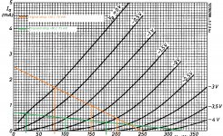
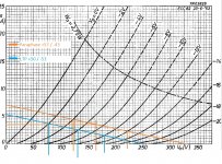
So to see if I have started to grasp load-line theory, I've attached a graph:
The original setup will be as per the brown curve lines, with a +/- 1V input generating a +50 / -70 volt output.
The proposed load-line with a 2K cathode resistor, higher plate resistor and increased supply voltage will be as per the green lines with the same input signal generating +80 / -75 volt output.
This corresponds to a gain improvement of 1.7 dB at a much lower distortion. The cost is the increased output impedance.
If I understand correctly increasing from approx. 42K up to 68K. I understand that this may have a negative impact on the input stage ability to drive the phase splitter and consequently the frequency respons.
The new tail voltage for the ECC82 phase splitter will be about 95 volts - is this sufficient for bias setting using a simple resistor or is CCS still recommended?
Grid voltage is about -26 Volts and 6L6 current approximately 66mA. I guess that means that my LTP need to swing between 40-50 volts p-p with Va-k of 230 volts.
On the 12AX7, try 100VP, 1V of bias, and 0.5mA of plate current. Make that 47K power supply dropper into 4.7K. Use a 500K plate loading resistor. Total resistance under the cathode drops to about 200 ohms. This will give you very high gain from the 12AX7 with very low distortion, and it will reduce the amount of voltage dropped across the CCS.
The LTP will give you some gain, but you need to lock down a number for the bias voltage on the output tubes, then work backwards to be sure your driver stage can deliver the goods.
So to see if I have started to grasp load-line theory, I've attached a graph:
The original setup will be as per the brown curve lines, with a +/- 1V input generating a +50 / -70 volt output.
The proposed load-line with a 2K cathode resistor, higher plate resistor and increased supply voltage will be as per the green lines with the same input signal generating +80 / -75 volt output.
This corresponds to a gain improvement of 1.7 dB at a much lower distortion. The cost is the increased output impedance.
If I understand correctly increasing from approx. 42K up to 68K. I understand that this may have a negative impact on the input stage ability to drive the phase splitter and consequently the frequency respons.
The new tail voltage for the ECC82 phase splitter will be about 95 volts - is this sufficient for bias setting using a simple resistor or is CCS still recommended?
Grid voltage is about -26 Volts and 6L6 current approximately 66mA. I guess that means that my LTP need to swing between 40-50 volts p-p with Va-k of 230 volts.
Attachments
Last edited:
Do plan to use a CCS, it makes a humongous difference in a LTP phase inverter.
The new load line for the AX7 looks good. Output impedance isn't earth shatteringly important here since the LTP doesn't have a ton of gain (keeping cMiller under control).
I'd aim for a little extra bias voltage on the LTP if you can get away with it.
The new load line for the AX7 looks good. Output impedance isn't earth shatteringly important here since the LTP doesn't have a ton of gain (keeping cMiller under control).
I'd aim for a little extra bias voltage on the LTP if you can get away with it.
- Status
- Not open for further replies.
- Home
- Amplifiers
- Tubes / Valves
- Modification paraphase to LTP.