I am building a line level switch box with a tube buffer that can be bypassed. I'm using mechanical rotary switches since my layout allows for the switches to be located near the I/O jacks. I'd like to add some LED indicator lights on the front panel to indicate which input and output channels are in use. Is there a simple way to do this without using relays? Could I rectify the 6.3V heater and run it through the same switch used to switch the channels?
You would need a separate unused part of the switch to do this. For example, while a 2 pole 6 way switch could be used for selecting up to 6 inputs, a 3 pole 4 way switch would allow up to 4 inputs and leave a spare pole on the switch to be used for input selection.
LED's are so efficient that they can be powered easily from any suitable supply. The heater winding is fine but would need a small rectifier and cap to derive a stable (ish) supply, otherwise you would notice the LED's flicker.
LED's are so efficient that they can be powered easily from any suitable supply. The heater winding is fine but would need a small rectifier and cap to derive a stable (ish) supply, otherwise you would notice the LED's flicker.
I'd prefer to avoid adding an additional power supply to the box (9V battery?) which is why I defaulted to the heater winding. The buffer circuit is a simple 12au7 cathode follower with 6CA4 rectified power supply. What other options do I have to supply the LEDs?
Last edited:
LED's need a DC current to illuminate and so at the very least you need a diode and a current limiting resistor to get them to work correctly from an AC winding. 50/60Hz flicker may be noticeable if you just left it at that.
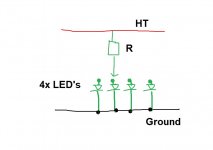
Modern LED's are so blindingly efficient that you could also realistically run them from the HT rail via a limiting resistor (or series resistors to spread the voltage). A current of 0.5ma would be more than enough for many high efficiency devices.
The switching is the problem unless you have the spare capacity unused on your present switches.
For a 300 volt HT line a 680k 0.25 watt series resistor could be all you need but you must either ensure that the resistor is specified for the voltage drop it sees (not power dissipated but voltage... resistors have voltage ratings as well) or use two or three equal value resistors to make up the required value. Each would only then see one half or one third the total voltage.
I've got two extra poles on each switch 😀! Any benefit you can think of by using HT instead of heater?
Using the HT is simpler (you just need a single suitable resistor) although you need to be aware that the switch contacts that are open will see the full HT value across them. Given the extremely low current I wouldn't really foresee an issue there tbh.
Using the HT is simpler (you just need a single suitable resistor) although you need to be aware that the switch contacts that are open will see the full HT value across them. Given the extremely low current I wouldn't really foresee an issue there tbh.
Hmmm... That may be a problem. I'm using Elma 04 switches that are rated at 42 VDC.
I know you won't want to draw much current from the HT rail if you go down that route... something which we would need to do to fiddle the switch issue.
This is how using the heater supply would look. The circuit is connected across the 6.3 volt winding. It doesn't matter if that winding is tied to ground or floated at some other voltage as it will supply just this circuit and nothing else.
The diode can be any 100v 1amp type. The cap (a 16 volt part is fine) isn't critical and can be relatively small because of the low current draw. The series resistor to the cap ensures the cap has an easy life. Alter R2 (which would go to the switch) to suit the LED brightness required.
Voltage source V1 in the diagram is the transformer winding.
Attachments

...rated at 42 VDC.
That may not be a real problem for a low non-reactive current. However you can add a resistor to Mooly's plan so the switch never sees 40V. The ~~half mA current may be enough in modern LEDs.
Attachments

I know you won't want to draw much current from the HT rail if you go down that route... something which we would need to do to fiddle the switch issue.
This is how using the heater supply would look. The circuit is connected across the 6.3 volt winding. It doesn't matter if that winding is tied to ground or floated at some other voltage as it will supply just this circuit and nothing else.
The diode can be any 100v 1amp type. The cap (a 16 volt part is fine) isn't critical and can be relatively small because of the low current draw. The series resistor to the cap ensures the cap has an easy life. Alter R2 (which would go to the switch) to suit the LED brightness required.
Voltage source V1 in the diagram is the transformer winding.
Is the purpose of the cap to smooth out the 60hz flicker? Why not use a diode bridge instead?
However you can add a resistor to Mooly's plan so the switch never sees 40V. The ~~half mA current may be enough in modern LEDs.
I've got a bag of THESE guys. Specs say "20-30mA." Should be OK on half mA, right?
Rather than routing hundreds of volt to drive a few LEDs, I much prefer the solution that used the heater winding. A WOG-style rectifier (Mouser P/N: 625-2W02G-E4, for example) and a 1000 uF, 16 V cap will fit anywhere and won't kill you if a wire comes undone. Then add a 1 kΩ series resistor for the LEDs and you're good to go.
Tom
Tom
I've got a bag of THESE guys. Specs say "20-30mA." Should be OK on half mA, right?
You may not get much light at 0.5 mA with those. I'd go for 5 mA (which is what I based my recommendation on above).
Now if Parts Express would just give you an actual data sheet, we'd be able to figure out how much less light you'd get at 0.5 mA, but they don't...
Tom
Modern LEDs are linear down to very low current. (I remember when they weren't.)
Modern LEDs are brighter than ever.
On another forum, stage musicians find 20mA drive (used in the early 1980s designs) way too bright with today's LEDs. They often up the resistor to 10K, 22K, sometimes higher; which on 9V supply runs about a half mA, as Mooly suggests.
At higher current, yes, I would favor taking heater AC. LEDs *will* run on AC, half the time. The reverse voltage is technically over the rating; I never killed one this way. (But someone says the newer ones may be more fragile?) They do flicker: if you move your head fast you see dotty-line instead of streak. The main problem is that it is poor design to bring AC onto your selector switch.
Is the purpose of the cap to smooth out the 60hz flicker? Why not use a diode bridge instead?
Two legs instead of four if you use an encapsulated bridge, two legs instead of eight if you use discrete. Keep it simple.
The current needed is so vanishingly small that the half wave single diode is perfect. You also don't need uV levels of ripple.
I've got a bag of THESE guys. Specs say "20-30mA." Should be OK on half mA, right?
Try one with a 9 volt battery and series resistor. A 12k would give a current of around 0.6ma.
Really high efficiency LED's would burn your eyes out at that current, older traditional types might be barely visible. So see what they need.
If you go down the heater route then you have enough current available to light dozens of even the lowest efficiency ones all simultaneously.
I'm now determined to rectify the AC heater to power the LEDs.
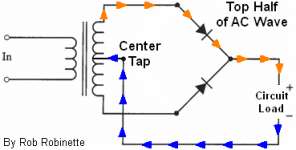
I've got a bag of THESE 1N4007 diodes. I'm familiar with a 1 diode half-wave rectifier (like what was posted in this thread) and a 4 diode full-wave bridge rectifier. What would a two diode bridge look like?
Two legs instead of four if you use an encapsulated bridge, two legs instead of eight if you use discrete. Keep it simple.
I've got a bag of THESE 1N4007 diodes. I'm familiar with a 1 diode half-wave rectifier (like what was posted in this thread) and a 4 diode full-wave bridge rectifier. What would a two diode bridge look like?
Last edited:
At higher current, yes, I would favor taking heater AC. LEDs *will* run on AC, half the time. The reverse voltage is technically over the rating; I never killed one this way. (But someone says the newer ones may be more fragile?) They do flicker: if you move your head fast you see dotty-line instead of streak. The main problem is that it is poor design to bring AC onto your selector switch.
I would definitely rectify the AC before sending it to my switch. I assume using a full-wave bridge would effectively eliminate the flicker? Whether or not I would actually perceive the flicker, if I could eliminate the risk with a couple extra $0.12 diodes then I say why not. My wife claims to be sensitive to the strobe effect - perhaps she'd be sensitive to the 60hz flicker as well.
I'm now determined to rectify the AC heater to power the LEDs.
I've got a bag of THESE 1N4007 diodes. I'm familiar with a 1 diode half-wave rectifier (like what was posted in this thread) and a 4 diode full-wave bridge rectifier. What would a two diode bridge look like?
I'll answer my own question... I believe this is what you had in mind, using the center tap as the return.
Attachments
- Status
- Not open for further replies.
- Home
- Source & Line
- Analog Line Level
- Input/Output Indicator LED Lights