When a low-power, HV supply source is required, for tube preamplifiers for example, the options available to DIYers tend to be limited: it is difficult to find off-the-shelf transformers combining low power (<10VA) and high secondary voltages (>150V).
The usual workaround is to connect two low-voltage transformers back-to-back, but this means twice the cost, twice the losses and twice the bulk.
If the supply is going to feed a shunt regulator, here is an interesting alternative:
The idea is to use a small mains transformer in reverse, and feed it via a capacitive supply: a capacitor is less bulky and less expensive than a transformer, and its losses are practically zero for modern dielectrics.
Such a supply inherently behaves like a wide compliance current generator, with the ballast consuming practically zero-power.
This means that the resistive part of the ballast can be reduced to almost nothing (not zero in general, because some resistance is still required for ripple elimination).
Advantages don't stop there: because of the current-mode operation, the no-load output voltage is much greater than with a transformer input: typically between 450 et 600V DC for a 230V transformer.
This gives much more room for regulation, even at 300V, than the transformer-based alternative, without resorting to voltage multipliers.
The supply is also inherently safe: the primary to secondary insulation of a transformer is the same as the secondary to primary, the capacitor provides an indefinite short-circuit protection, and the saturation of the iron limits the open-circuit secondary voltage (it can be artificially reduced to some arbitrary value by using a suitable varistor).
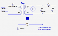
Here is an example I tested with a 2VA transformer.

The 470nF dropping capacitor is selected to stay below the maximum secondary (now the primary) current of the transformer: 2/48=42mA. The short-circuit current is 34mA, <42mA.
In these conditions, the open-circuit output voltage is 550V.
As I didn't use a bleeder or voltage limiter for the tests, I used a PIO capacitor rather than an E-cap, but in real life, the 550V drops quickly as soon as a little current is drawn.
The equivalent internal resistance is 140K. This is an approximate value, because the real behavior is somewhat non-linear, and the actual, physical short-circuit current is closer to 7mA than 4mA, but for practical purposes, with realistic output voltages, the 140K is a good approximation.
This supply could feed a shunt regulator having a voltage anywhere between 0 and 350V.
Needless to say that you have to observe all of the usual precautions for mains-connected circuits, and the dropping capacitor must be a X-type, for across the mains applications
The usual workaround is to connect two low-voltage transformers back-to-back, but this means twice the cost, twice the losses and twice the bulk.
If the supply is going to feed a shunt regulator, here is an interesting alternative:
The idea is to use a small mains transformer in reverse, and feed it via a capacitive supply: a capacitor is less bulky and less expensive than a transformer, and its losses are practically zero for modern dielectrics.
Such a supply inherently behaves like a wide compliance current generator, with the ballast consuming practically zero-power.
This means that the resistive part of the ballast can be reduced to almost nothing (not zero in general, because some resistance is still required for ripple elimination).
Advantages don't stop there: because of the current-mode operation, the no-load output voltage is much greater than with a transformer input: typically between 450 et 600V DC for a 230V transformer.
This gives much more room for regulation, even at 300V, than the transformer-based alternative, without resorting to voltage multipliers.
The supply is also inherently safe: the primary to secondary insulation of a transformer is the same as the secondary to primary, the capacitor provides an indefinite short-circuit protection, and the saturation of the iron limits the open-circuit secondary voltage (it can be artificially reduced to some arbitrary value by using a suitable varistor).
Here is an example I tested with a 2VA transformer.
The 470nF dropping capacitor is selected to stay below the maximum secondary (now the primary) current of the transformer: 2/48=42mA. The short-circuit current is 34mA, <42mA.
In these conditions, the open-circuit output voltage is 550V.
As I didn't use a bleeder or voltage limiter for the tests, I used a PIO capacitor rather than an E-cap, but in real life, the 550V drops quickly as soon as a little current is drawn.
The equivalent internal resistance is 140K. This is an approximate value, because the real behavior is somewhat non-linear, and the actual, physical short-circuit current is closer to 7mA than 4mA, but for practical purposes, with realistic output voltages, the 140K is a good approximation.
This supply could feed a shunt regulator having a voltage anywhere between 0 and 350V.
Needless to say that you have to observe all of the usual precautions for mains-connected circuits, and the dropping capacitor must be a X-type, for across the mains applications
Attachments
Needless to say that you have to observe all of the usual precautions for mains-connected circuits, and the dropping capacitor must be a X-type, for across the mains applications
I am not in a position to comment on the safety aspects of this whole setup. However, I believe that X type caps tend to short in case of a failure. This would put the whole unattenuated mains on the secondaries of the transformer wired backwards. That does not sound like a good thing to me.
X caps are not intended to fail short, and most do not. They are widely used as capacitive droppers, and the usual problem is that they slowly lose capacitance as each overvoltage event burns away a bit more metal film.
A remarkable piece of skewed information.
The confusion probably stems from the distinction between X and Y capacitors.
The Y capacitors may never fail in a conductive way, short or increased leakage.
The X capacitors are exempted from this requirement, but this does certainly not imply that they are supposed to fail short, quite the opposite in fact.
But in case they short (momentarily), they cannot start a fire: basically, the shallow metallization acts as a fuse and opens the circuit before things go really wrong, but if a X capacitor is used in a Y situation, the current through the human body won't be sufficient to clear the defect and there is a risk of electric shock.
As with anything connected to the mains, it is advisable to use suitable protection means, series fuse, discharge resistors, etc
I do not see how: the only place where the current would be naturally sufficient is on the primary side, and relying on the cathode to heater insulation for safety seems foolhardy at the very least, if not suicidal.
Such schemes might have been used decades ago, when cars had no safety belts, men were real men, spirits were stiffer and grass was greener, but nowadays they no longer stand...
Such schemes might have been used decades ago, when cars had no safety belts, men were real men, spirits were stiffer and grass was greener, but nowadays they no longer stand...
Member
Joined 2009
Paid Member
Thanks Elvee! Still, very useful design as is!I do not see how: the only place where the current would be naturally sufficient is on the primary side, and relying on the cathode to heater insulation for safety seems foolhardy at the very least, if not suicidal.
Such schemes might have been used decades ago, when cars had no safety belts, men were real men, spirits were stiffer and grass was greener, but nowadays they no longer stand...
A remarkable piece of skewed information.
The confusion probably stems from the distinction between X and Y capacitors.
The Y capacitors may never fail in a conductive way, short or increased leakage.
The X capacitors are exempted from this requirement, but this does certainly not imply that they are supposed to fail short, quite the opposite in fact.
Ok, so would it be wise to recommend a Y capacitor instead of an X to reduce the risk of full mains at the secondaries of the backwards transformer?
Why not, but if you follow that kind of logic, you should also replace practically every single X cap in your environment (and there are many!) with Y caps.
In fact, X caps would become redundant.
In practice, if your concerns about mains on the secondary turn to obsession, you simply have to add a 100 or 250mA fuse: transformers are very tolerant of short-term overload events, even huge ones.
Note that many X caps in the real world are unfused, and most of those that are aren't intentionally: a fuse just happens to be upstream, and it has certainly not been dimensioned with the cap in mind.
As I said, the main problem with X caps is that the self-healing mechanism causes them to slowly lose capacitance. I have had to replace cap droppers in a doorbell and an oven timer because 6 or 7 years of use meant that the cap value had more than halved.
Why not, but if you follow that kind of logic, you should also replace practically every single X cap in your environment (and there are many!) with Y caps.
In fact, X caps would become redundant.
In practice, if your concerns about mains on the secondary turn to obsession, you simply have to add a 100 or 250mA fuse: transformers are very tolerant of short-term overload events, even huge ones.
Note that many X caps in the real world are unfused, and most of those that are aren't intentionally: a fuse just happens to be upstream, and it has certainly not been dimensioned with the cap in mind.
Ok, here's my line of thinking:
If an X type capacitor in its intended "across the mains" application fails by shortening, it will cause a short between the mains. The this will blow a fuse (possibly in the mains house installation).
If the X type capacitor fails by shortening in the application described above, it will put full mains voltage to the secondaries of the backwards transformer. If the transformer survives this, the voltage on the primaries will be in the kilo-Volt range. This might destroy the rectifier, the smoothing cap, or whatever is connected to the DC output. If it does not blow a fuse (why would it?), the kilo-Volts would still be present at the transformer. That might be considered (too) dangerous in some environments.
Don't mess with high voltages!
Ok, here's my line of thinking:...If the X type capacitor fails by shortening in the application described above, it will put full mains voltage to the secondaries of the backwards transformer....
If you put mains voltage on a small 24V winding, current will get LARGE. I have dimmed the room lights by momentarily doing this on a 24VA transformer (oops). Among other things, much over 30V on a "24V" winding saturates the core and inductance falls very low.
Elvee has proposed a 2VA core. This may have 60 Ohms of DCR. This will draw only 4 Amps from the wall, so will NOT blow the house fuse. Most of the 960 VA drawn appears as heat in the 2VA transformer's one winding and it will POOF! in a quick cloud of smoke. True, in that moment the other winding will show high voltage, but probably not even 2X the factory nominal voltage due to core saturation.
A fuse or small flame-proof resistor does seem wise.
PRR took the words of my mouth: 50/60Hz transformers are designed rather tightly for economic reasons, and they will have difficulty passing more than twice their rated voltage; pulse waveforms could go much higher, but the rectifier + filter cap will clip them easily.
Thus, the secondary voltage is not a real issue.
What remains is the issue of a dead-shorted cap combined with a low resistance winding; it is in principle a problem, because the winding in question may catch fire.
In practice, this doesn't seem to be a problem: most of the failed caps do so by by going open or loosing capacitance as DF mentionned.
From my experience (hundreds+ failed samples) the minority that don't follow the stereotype do fail in the nastiest possible way: their leakage current increases until they overheat and smoulder (and would you believe it, Rifa amongst all is one of the foremost culprit in this respect: even them managed to get something wrong in the design or manufacture of their X-caps; that's probably documented somewhere on the net).
That is the worst possible way to fail for an X-cap, and that's precisely what the standards try to avoid.
This kind of failure will not be caught by a fuse or any other protection measure, except the new technologies analyzing the signature of a fault current (noise, randomness, etc).
It won't harm the transformer either, because the current remains relatively low.
By contrast, I have never encountered a dead-short on a X-cap: there must be instances though, but they are certainly very rare, because the healing mechanism is an essential prerequisite for such caps.
For this relatively unlikely instance, an ordinary fuse is a sufficient protection.
Note that many small mains-fed appliances using a capacitive supply are not fused, and do not have a fusible surge-limiting resistor upfront: they do not seem to pose a problem, otherwise safety authorities would have issued warnings, which does not seem to be the case.
Anyway, the best practice is to always fuse anything connected to the mains or to an ~unlimited source of power
Or you could use one of these and power the preamp from a 12V brick.
I've had one powering a dual 6SN7 preamp for 3 years now. Heaters in series off the same 12V supply as the boost module.
DC-DC 8-32V to +-45V-390V Step-up ZVS High Voltage Capacitor Module Charge Board | eBay
I've had one powering a dual 6SN7 preamp for 3 years now. Heaters in series off the same 12V supply as the boost module.
DC-DC 8-32V to +-45V-390V Step-up ZVS High Voltage Capacitor Module Charge Board | eBay
Or you could use one of these and power the preamp from a 12V brick.
I've had one powering a dual 6SN7 preamp for 3 years now. Heaters in series off the same 12V supply as the boost module.
DC-DC 8-32V to +-45V-390V Step-up ZVS High Voltage Capacitor Module Charge Board | eBay
What's the max. output current of these? Maybe I am blind, but I couldn't find this in the description.
I'm guessing 200 ma. However, I derate them to 10W because I run them in 50c ambient. That means 25ma @ 390V, enough for the average preamp
Hello kodabmx,
are these modules really zero voltage switching, as claimed? Did you test their high frequency noise output?
are these modules really zero voltage switching, as claimed? Did you test their high frequency noise output?
- Status
- Not open for further replies.
- Home
- Amplifiers
- Power Supplies
- A simple, cheap, safe and reliable alternative source for low-power HV shunt supplies