Hi all,
I am planning a TL cabinet for a 8'' woofer, 3 way spk
Can place the open port at the rear panel, if the spk is about 1.5 meter away of the wall
Any idea and advice is very well come
Best regards,
williams
I am planning a TL cabinet for a 8'' woofer, 3 way spk
Can place the open port at the rear panel, if the spk is about 1.5 meter away of the wall
Any idea and advice is very well come
Best regards,
williams
I have built many TLs, both with tapered lines or mass-loaded lines and virtually all of them had the terminus or mass-loading port located on the rear panel. Due to room limitations, all of my cabinets sit on a floor-level fireplace hearth with their backs 4 to 8 inches from the wall, depending on cabinet depths, with no performance issues caused by the close proximity to that wall. With a spacing of 1.5 meters, you will absolutely NOT have a problem.
Paul
Paul
Hi all,
I am planning a TL cabinet for a 8'' woofer, 3 way spk
Can place the open port at the rear panel, if the spk is about 1.5 meter away of the wall
Any idea and advice is very well come
Best regards,
williams
Thanks Paul, this is very helpful to learn from your experience
This will help my design
Williams
This will help my design
Williams
Dave,
It will be a 3 way active system, active analog xover
I am starting as a prototype and need some help and advices
In the past I built the Radford s90, the bass was good the rest ..... so and so.
I am forced the use a rear port for the TL
Thanks for your time.
Best regards,
Williams
Attachments
I cleaned up your document to make it easier to read (and way smaller).
Rear vent is no issue.
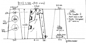
What you have drawn is sort of an ML-TL with a pre-chamber and a bit of a driver offset. I’d have to do the math to figure out whether the decrease in line depth x the increase in line width yields an untapered line or something else.
Did you model this? Or is it seart-of-the pants? If it is you are something like 90% assured of getting something far from optimal.
dave
Rear vent is no issue.
What you have drawn is sort of an ML-TL with a pre-chamber and a bit of a driver offset. I’d have to do the math to figure out whether the decrease in line depth x the increase in line width yields an untapered line or something else.
Did you model this? Or is it seart-of-the pants? If it is you are something like 90% assured of getting something far from optimal.
dave
15x30 = 450
8x50=400
so a slight taper.
also in the notes you specify 100w woofer — power handling is not a spec that is worth giving any serious attention.
dave
8x50=400
so a slight taper.
also in the notes you specify 100w woofer — power handling is not a spec that is worth giving any serious attention.
dave
Hi Dave,
Thanks for the answer. Very nice of you.
The idea is from RADFORD S90 I built long ago.
This one, is very basic calculation of 1/6 wave length, the TL is about 2m long, 2x6=12 , 340/12=28.3 Hz; just like this, the size of the port 1/3 of the woofer effective surface which is 220 cm², so is 14x5.5 cm, I don’t have any other calculations.
The enclosure is tapered like a trapezoid, not to complicate it too much suppose it is rectangular, will ease the calculations.
If you know what software is available, or basic calculus, it can help me very much.
Best regards.
Williams
The Radford S90 really made an impression on me when i 1st heard it in the early 1970s and lead to a facination with TLs.
Bt throw that all out. None* (well not much) of classic TL is worth anything. Get a hold of Leonard Softwares TL Modeller (thread here) or HornResponse and model the line.
*for intstance, the Sd of a driver has nothing to do with designing a TL. Like all other boxes Fs, Qts, Vas are what impact the line.
Start by reading everything here: Quarter Wavelength Loudspeaker Design
dave
A 1/6-wavelength line length! Why?
Paul
Paul
Hi Dave,
Thanks for the answer. Very nice of you.
The idea is from RADFORD S90 I built long ago.
This one, is very basic calculation of 1/6 wave length, the TL is about 2m long, 2x6=12 , 340/12=28.3 Hz; just like this, the size of the port 1/3 of the woofer effective surface which is 220 cm², so is 14x5.5 cm, I don’t have any other calculations.
The enclosure is tapered like a trapezoid, not to complicate it too much suppose it is rectangular, will ease the calculations.
If you know what software is available, or basic calculus, it can help me very much.
Best regards.
Williams
Paul, i missed that… A pipe is only ever a half wavelength resonator (both ends open or closed) or a quarter wavelength resonator (one ends open, one end closed).
dave
dave
Hopefully it's not that 1/6 wavelength twaddle from a few years back. I remember sitting that one out, mainly because I was unable to type due to rolling on the floor. 😀
For the OP: just to repeat what Dave said & Paul hints at. You can't have a 1/6 wave TL in this physical reality.
-A pipe open at both ends is a 1/2 wave resonator.
-A pipe open at one end and closed at the other is a 1/4 wave resonator.
Those are what the laws of physics dictate. You can certainly have one of those general types of pipe tuned to 1/6 wavelength of a particular frequency, but that's just an unnecessarily complicated way of saying you've a pipe of either type tuned to a higher frequency. 😉
That's exactly what caused me to ask the question about why 1/6 wavelength line. I do remember the same twaddle and couldn't believe what I was reading from that idiot.
Paul
Paul
Hopefully it's not that 1/6 wavelength twaddle from a few years back. I remember sitting that one out, mainly because I was unable to type due to rolling on the floor. 😀
For the OP: just to repeat what Dave said & Paul hints at. You can't have a 1/6 wave TL in this physical reality.
-A pipe open at both ends is a 1/2 wave resonator.
-A pipe open at one end and closed at the other is a 1/4 wave resonator.
Those are what the laws of physics dictate. You can certainly have one of those general types of pipe tuned to 1/6 wavelength of a particular frequency, but that's just an unnecessarily complicated way of saying you've a pipe of either type tuned to a higher frequency. 😉
Except that the line shortens when tapered for the same tuning correct? Maybe that's the source of the 1/6 length notion, as that would be close to what a 8:1 line does (I think).
But this is a pre-chamber + a very slightly tapered pipe. With a restricted terminus and a driver offset. Too complicated to even guess. Needs to be modelled.
dave
dave
I found the 1/6 wave calculation in a kind of article, with tapered line as I wrote.
But I really like to see a real made project with basic calcs, that can enlighten me.
I think that always is a pre chamber and then the TL, can be linear or tapered, no? My woofer is Scan-speak 21W/8555-00 8'' .
I was reading the
Perry S. Marshall
A Derivation and Analysis of the Transmission Line Speaker Enclosure
A Report for Electrical Engineering 498M Topics in Acoustics and Audio
University of Nebraskaת Fall, 1990
He is talking about 1/4 wave TL, so the 1/6 wave TL is some wrong choice.
Very difficult finding an easy formula, for a given woofer.
Williams
The real TL models came in Fall 1999, everything before that should be tossed.
Prechambers are little used in modern TLs, usually you see a tapped line, often lines (usually straight-ones) will have a restricted terminus (ML-TLs).
Your concept does lend itself to a pre-chamber.
For some real-worl examples, read the stuff at quarter-wave.com (linked earlier). This from the guy that has done the basic work that has completely modernized TL design. Then look for modern TL designs from Scott Lindgren (Scottmoose*), Paul Kittinger (pkitt), Greg Monfort (GM), and Bob Brines to name the 1st ones that pop off my head.
*(i — planet10 — will often be associated with Scott’s work since i do the drawings)
dave
Thanks for including me in your last paragraph, Dave, along with the others, but just to clarify, my full last name is Kittinger, and I have two user names, depending on the forum, pkitt and Paul K.
I've used quite successfully a couple of times what might be called pre-chambers, but better defined by George Ausperger as coupling chambers.
Paul
I've used quite successfully a couple of times what might be called pre-chambers, but better defined by George Ausperger as coupling chambers.
Paul
The real TL models came in Fall 1999, everything before that should be tossed.
Prechambers are little used in modern TLs, usually you see a tapped line, often lines (usually straight-ones) will have a restricted terminus (ML-TLs).
Your concept does lend itself to a pre-chamber.
For some real-worl examples, read the stuff at quarter-wave.com (linked earlier). This from the guy that has done the basic work that has completely modernized TL design. Then look for modern TL designs from Scott Lindgren (Scottmoose*), Paul Kitt (pkitt), Greg Monfort (GM), and Bob Brines to name the 1st ones that pop off my head.
*(i — planet10 — will often be associated with Scott’s work since i do the drawings)
dave
- Status
- Not open for further replies.
- Home
- Loudspeakers
- Multi-Way
- TL cabinet rear port