Hi
I want to design half-bridge smps from 220 volts(AC) and with the output voltage at about 24 volts and 100 watt .
Vin=220 volts AC
Vout=24 volts DC
Pout=100 watt
I dont want to use more iron transformer for the supply voltage of the sg3525 and I want to use auxiliary winding for genetating 12 volts for supplying the sg3525.
Can I use this auxiliary winding? Please help me for doing this.
Regards,
I was a bit surprised to see that...
http://www.ti.com/lit/ds/symlink/uc1525b.pdf
Whilst Under Voltage Lock Out and Soft Start is mentioned there is no reference to the supply current when the IC is in Under Voltage Lock Out.
Compare with,
http://www.ti.com/lit/ds/symlink/uc2846.pdf
http://www.ti.com/lit/ds/slus235a/slus235a.pdf
http://noel.feld.cvut.cz/hw/philips/acrobat/5060.pdf
Which all appear to have the supply current specified as being 1mA when in Under Voltage Lock Out.
The idea is that you can provide the start up supply from the main DC bus, 311V?, with a simple resistor and local decoupling suitably scaled for the amount of hysteresis by picking the value of your resistor to satisfy the 1mA requirement. Pick say 1.5mA and use 2 off 100K, voltage and power rating.
Whether the SG3525 does implement such a methodology is open to question so I would be inclined not to use it.
... Oh the UC1846 is a current mode controller so may not play nice with the Half Bridge unless you get into implementing flux balancing windings. The UC3825 can be used for both voltage mode and current mode control so might be a better choice. I guess there is more modern stuff about the place as well.
Last edited:
Thanks you so much for the answer.
It is the bootstrap circuit.

This is a boostrap winding, which as you require, will supply the IC's operating current.
Before the unit starts operating though. you still require a startup circuit, which takes the high voltage rectified DC and drops it to the lower voltage required to start the IC.
The simplest implementation is a power resistor, a capacitor and a zener, as simple as that.
Having said this, when you do your calculations, you will realize that dropping from 310 to 10 volts DC with a startup current of 30 or more mA like the 3525, the resistor and zener will be very, very large.
This is because the SG3525 wasn't designed for transformerless line startup. Newer devices have startup currents of perhaps 1 mA or lower, allowing for much smaller components.
It is the bootstrap circuit.
This is a boostrap winding, which as you require, will supply the IC's operating current.
Before the unit starts operating though. you still require a startup circuit, which takes the high voltage rectified DC and drops it to the lower voltage required to start the IC.
The simplest implementation is a power resistor, a capacitor and a zener, as simple as that.
Having said this, when you do your calculations, you will realize that dropping from 310 to 10 volts DC with a startup current of 30 or more mA like the 3525, the resistor and zener will be very, very large.
This is because the SG3525 wasn't designed for transformerless line startup. Newer devices have startup currents of perhaps 1 mA or lower, allowing for much smaller components.
Hi. This sounds like a problem I have had recently. I am a bit new to SMPS but I came up with a solution that seems to work pretty good. I figured that you only need the current but for a short time which sounds like a capacitor situation.
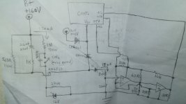
 I sketch out the relevant circuit section. It may not be exactly your situation but maybe you can adapt. My situation is with a non-isolated controller, starting a TL494 and gate drive transformer for an asynchronous 1/2 bridge from 120VAC rectified mains. Then using an auxiliary winding from the power transformer to take over duty providing Vcc to the control circuit. But then also switch off with the switch.
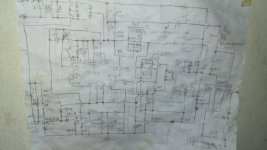
In this case referring to the first pic, when the switch is closed, the 2.2uf cap in series with the collector of transistor provides charge in order to start and the auxiliary winding/rect takes over. When the switch, which can be small but mains rated is opened, the comparator circuit interrupts the controller by way of error input and the circuit unlatches. Also thermistor thrown in there can trigger comparator. Seems to work, at least in practice.😛. Second pic is the circuit mock up sketch that I used in with minor corrections and it had a drink spilled on it...oops😀
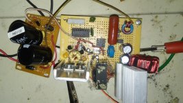
 but it will be redrawn in CAD for PCB soon anyway. Third pic is the experimental circuit.
If you are using 310V B+, you can scale up values, maybe adjust cap value to suit the needed current but use at least 400V, should use 1/2W size resistors where voltage constraints require, and 400V Transistor. I used 2N6517 but it will not reach 310V.😛. Anyway, maybe you will get ideas.🙂
I figured that you only need the current but for a short time which sounds like a capacitor situation. I sketch out the relevant circuit section. It may not be exactly your situation but maybe you can adapt. My situation is with a non-isolated controller, starting a TL494 and gate drive transformer for an asynchronous 1/2 bridge from 120VAC rectified mains. Then using an auxiliary winding from the power transformer to take over duty providing Vcc to the control circuit. But then also switch off with the switch. In this case referring to the first pic, when the switch is closed, the 2.2uf cap in series with the collector of transistor provides charge in order to start and the auxiliary winding/rect takes over. When the switch, which can be small but mains rated
is opened, the comparator circuit interrupts the controller by way of error input and the circuit unlatches. Also thermistor thrown in there can trigger comparator. Seems to work, at least in practice.😛. Second pic is the circuit mock up sketch that I used in with minor corrections and it had a drink spilled on it...oops😀 but it will be redrawn in CAD for PCB soon anyway. Third pic is the experimental circuit.If you are using 310V B+, you can scale up values, maybe adjust cap value to suit the needed current but use at least 400V, should use 1/2W size resistors where voltage constraints require, and 400V Transistor. I used 2N6517 but it will not reach 310V.😛. Anyway, maybe you will get ideas.🙂
Attachments
Last edited:
Of course you can, just have one more secondary that will create about 12v for you from main transformer.Hi
I want to design half-bridge smps from 220 volts(AC) and with the output voltage at about 24 volts and 100 watt .
Vin=220 volts AC
Vout=24 volts DC
Pout=100 watt
I dont want to use more iron transformer for the supply voltage of the sg3525 and I want to use auxiliary winding for genetating 12 volts for supplying the sg3525.
Can I use this auxiliary winding? Please help me for doing this.
Regards,
More important question is, is your SG on primary side or on secondary. This will determine how simple circuit you would need to get SG going on power on
From this I will assume, you have SG on primary side. And this is exactly what you need, so called power zener. This will drop 300v+ down to above 10v for SG, at which point SG will start to work. And if you have secondary voltage for SG also, which is above the one from power zener, it will supply itself from there and not from zener itself. Which means, power dissipation in power zener will be high, but VERY short and won't be any problem.Thanks you so much for the answer.
It is the bootstrap circuit.
Having said this, when you do your calculations, you will realize that dropping from 310 to 10 volts DC with a startup current of 30 or more mA like the 3525, the resistor and zener will be very, very large.
This is because the SG3525 wasn't designed for transformerless line startup. Newer devices have startup currents of perhaps 1 mA or lower, allowing for much smaller components.
Find my supply and see how that looks like
- Status
- Not open for further replies.
- Home
- Amplifiers
- Power Supplies
- Starting up SG3525 with auxiliary winding