Ian,
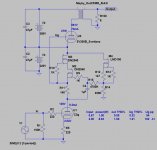
Current through 300B flows through "its"/upper PSU.
The schematic does not show the resistors across the PSU caps to allow DC current flow.
Osprey, you are wellcome.
Also try with gyrator. So you will avoid a big choke.
With 5K OPT you will get about 0.2% THD at full power for 300B.
Why not taking the 300B grid input from the mu output of the DN2540 gyrator? Bootstrapping of the source resistor will improve the linearity of the C3g driver
Thanks
Ale

Right. I just wanted to point that out that the lower psu only references the upper. But as a reference, it needs to be quiet, or the noise will add to the upper.
I think that if one used a "statistical regulator", it might be possible to take the gyrator reference right off the zener stack. 😉
I think that if one used a "statistical regulator", it might be possible to take the gyrator reference right off the zener stack. 😉
Why not taking the 300B grid input from the mu output of the DN2540 gyrator? Bootstrapping of the source resistor will improve the linearity of the C3g driver
Thanks
Ale
Will it then still be direct coupled? 🙄
Not that I think it is a bad idea though.
C3gT cascode gyrator loaded, direct coupled 300B SE.
BTW it's "simple", but hyper sensitive to the driver tube operating point (V1 anode voltage), so tube's aging would be destroy 300B!
BTW it's "simple", but hyper sensitive to the driver tube operating point (V1 anode voltage), so tube's aging would be destroy 300B!
Attachments
Last edited:
You're right, Bela. But on that op. point C3g (1.4 W of dissipation) can work 20-30 years.
I remember it from my old "postal" days.
I remember it from my old "postal" days.
Some answer on e-mail questions I received:
- For "no capacitor cleaners": Instead of the last capacitors in PSU`s you can put VR tubes.
- For those who do not use C3g, you can put driver tube you want. In that case (considering the Bala comment), you can put a fuse after rectifier in the PSU for output tube B+.
Best diying.
- For "no capacitor cleaners": Instead of the last capacitors in PSU`s you can put VR tubes.
- For those who do not use C3g, you can put driver tube you want. In that case (considering the Bala comment), you can put a fuse after rectifier in the PSU for output tube B+.
Best diying.
C3gT cascode gyrator loaded, direct coupled 300B SE.
BTW it's "simple", but hyper sensitive to the driver tube operating point (V1 anode voltage), so tube's aging would be destroy 300B!
Actually, I think the 300b will not last as long as the c3g, but decline will not due to aging of the c3g.
I might breadboard it again with 2a3, using a statistical regulator on the lower power suppy. I think it can be designed so that even if the driver tube is pulled, it will not get destroyed.
Maybe you could use a resistor and a zener stack instead of the LND150 CCS loaded shunt... 😉 and you already have a zener stack in the statistical regulator.. (oops I said too much maybe).
Ian
Why too much ???
I like your ideas. When I find a power transformer and order 2A3, I will do something with this amp.
I like your ideas. When I find a power transformer and order 2A3, I will do something with this amp.
Nice to see a 5K load on the 300B - euro21 - once the inductive part of the load is included the suggested resistive load does not always work .
I think that if one used a "statistical regulator",...
Ian,
What should be the maximum voltage ripple on the input of the statistic regulator?
Is CRC enough before?
I do not have any experience with that regulator.
Thanks
From Morgan Jones' Valve Amplifiers (4th Edition):
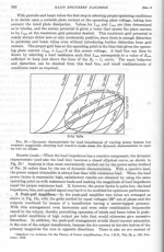
"The statistical regulator is certain to have >90dB ripple attenuation, so this corresponds to it tolerating 53Vpk-pk ripple post rectification."
Of course it pays to read his book in full. The circuit is not at all complex and he explains it in great detail.
Ian
"The statistical regulator is certain to have >90dB ripple attenuation, so this corresponds to it tolerating 53Vpk-pk ripple post rectification."
Of course it pays to read his book in full. The circuit is not at all complex and he explains it in great detail.
Ian
Last edited:
Member
Joined 2009
Paid Member
I thought this thread had ruled out use of sand, the 'statistical regulator' uses a sand based current source. I have thought about using a tube-based CCS but it does make the thing more difficult and if you want anything remotely close in terms of performance I would imagine it getting complicated.
Specifications are sometimes cleverly "stretched".
When you take a close look at the frequency curve of your example, it is obvious that it includes the first resonance.
The real curve starts falling at about 30 kHz.
Monolith Magnetics ? - simply has to be who else specifies 7Hz - 151kHz so specifically?
THEY state very clearly that stated BW is without resonance, so how to counter that?
Knowing resonance is when Xl = Xc... looking at the (f) vs amplitude plots, how can you arrive at such a conclusion?
I suppose you know this guys math/ physics is at a very high level, Phd level, and he lectures in that/those subject/s.
There is a commercial amplifier which openly admits to using these OPT, claims measured BW out to >140kHz in circuit, retails for 25k USD
The Truth | Whammerdyne Heavy Industries
Have to say that I am leaning toward thinking that you are short on this one.
Hanze.
Hi Hanze
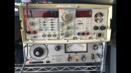
Sure you may see something around 100kHz on the Tektronix I have but it will be over 30 dB down
Such a load of crap
Sure you may see something around 100kHz on the Tektronix I have but it will be over 30 dB down
Such a load of crap
- Status
- Not open for further replies.
- Home
- Amplifiers
- Tubes / Valves
- Single Ended 2A3/6A3/6B4G DC coupled & Transformer choices