Depending on what exactly you mean, this could be a big mistakeI am not trying to reproduce a signal: I try to reproduce musical instruments, and to make believe, across absolutely not hifi speakers, that those instruments are in my listening room.
At his time, he made the mixing desks the most appreciated by the majority of sound engineer that i know or knew. And on his desks were produced so many master pieces !Would you assert that Rupert Neve's design was *optimal*? I'd hope not, although I hope (and believe) it does what it's supposed to do.
I remember those fights with the Automated process mixing desks, trying to get something "living", while just pluggin the same mike in a NEVE, and .... Bingo.
Both were expensive, both where automated, both had close performances on paper. But Ruppert did not agreed the sound of VCAs, so, if I remember well, he invented flying faders. As it was impressive for the customer, to see those faders moving by their own, Automated Process adopted the principle, but with... VCAs.
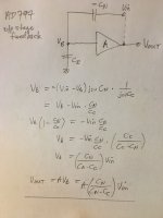
Scott, please tell me whether this is a fair representation of the output "distortion cancellation" scheme of the AD797? I find it easier to examine by equations. I've set Cn negative instead of showing the current mirror for simplicity. I also assume that Va=Vb (in the data sheet Fig 33) so I only need to consider Vb.No need to say that, it is easy to demonstrate the effect it's just that giving it a name has been difficult. I never compared plots of w/wo HEC but that might be interesting. It was just that when a simple cap between two nodes on the bootstrapped current mirror gave this effect I was surprised, there is virtually no added circuitry to get this benefit.
I have deliberately cut the feedback path to calculate the open loop equation Vout/Vin.
The result is an infinite open loop gain when Cn=Cc. This is the hypothetical condition for so-called "error cancellation". This is what reminds me of HEC which seems to me to propose the same hypothetical scheme. Naturally, infinite gain is not possible in practice and approaching it will result in unavoidable instability. Additional compensation is always required to keep the thing stable and this necessarily makes the scheme a standard NFB loop, as Hawksford later conceded.
My challenge to the data sheet is where it states:
Which I do not agree with because the practical implementation has to be a standard NFB loop in which distortion is ratiometrically reduced (assuming it's stable) and not "canceled" by simple subtraction or otherwise. Unless I have made a mistake, the maths does not support this IMO.In Figure 33, the terms of Node A, which include the properties of
the output stage, such as output impedance and distortion, cancel
by simple subtraction.
Attachments
Last edited:
Well, of course, distortion, bandwidth and linearity, slew rate, damping, every technical aspect has to be good enough.Depending on what exactly you mean, this could be a big mistake
I was talking about subtle sound details. You know, the difference between film caps and electrolytics, good and oversized resistances in the feedback path at low enough impedance , oversized power supplies and critical rails/speaker cables and printed circuit paths. Non magnetic chassis, non resonant radiators etc...
Not to talk about topologies, FET VS bipolar, CFA VS VFA, Class A VS class B VS class D etc ...
All those details and a lot more, that, placed end to end, makes a difference. At least to me.
(And, please, I'm not talking about outpriced esoteric components, a good quality price ratio matters more than subtle differences.;-)
Last edited:
I agree with you Tournesol, we HAVE to listen openly in the end, to whether we have made a successful audio product. In fact, we may have to have others openly listen to our designs before we are sure that we have a successful sounding design. We don't need double-blind testing for this.
Ok, it doesn't mean what I thought it might mean, that doesn't mean I know what it means, if you know what I mean
In the end, what can this tell you? Only if there's a difference?We don't need double-blind testing for this.
I have no idea what you mean.Ok, it doesn't mean what I thought it might mean, that doesn't mean I know what it means, if you know what I mean
It's fun having the analogy, but the reason F1 drivers are better than the rest of us has way less to do with reactions (feedback) than a sophisticated feedforward mechanism. There's been plenty of tests that show many/most drivers don't have catlike reflexes (although they obviously know what to do to react) but rather see things coming long before the rest of us do.
Fun aside, don't take anything else from it.
It paints a horrible, bloody, picture if you think about an F1 driver trying to race a coarse they haven't driven a couple times.
It's probably more important to have track recall, than to have reflexes for them. Where as some other sports people do have better reflexes (cat like? I dunno, what does that even mean).
I agree with you Tournesol, we HAVE to listen openly in the end, to whether we have made a successful audio product. In fact, we may have to have others openly listen to our designs before we are sure that we have a successful sounding design. We don't need double-blind testing for this.
While most designing has been successful without it, if you knew it could be done in a manner where the results were not null, would you use it ever? Maybe do a serious of tests on things you aren't always sure about?
Hi Tournesol,
Every single product I have seen designed solely by ear has been a disaster. You've got to design and measure and measure and measure, then you listen and alternate measuring and listening. You can't get a good product without the instruments and ears. By doing both, you ensure that your design truly does reproduce music accurately. Depending on the source material, you can put the soul of the piece back out into the room.
-Chris
Which I do not agree with because the practical implementation has to be a standard NFB loop in which distortion is ratiometrically reduced (assuming it's stable) and not "canceled" by simple subtraction or otherwise. Unless I have made a mistake, the maths does not support this IMO.
No it doesn't review neutralization of input capacitance on RF amplifiers, A can be 1 and you simply have C and -C, but A has a BW limitation even though it only has a magnitude of 1 at the limit you have 90 degrees of phase and -3dB and lose the cancellation.
Look at it this way, at the unity gain BW frequency the distortion in both cases is the same but with the error correction the distortion falls as 1/f squared while without it falls as 1/f. Take most popular amplifier's distortion vs frequency plots and you will see the rising THD at high frequencies, now superimpose a rising THD that starts later but intercepts the first at the UGBW.
didn't know the name, yet they have his book at the local library. Will have a look into it. Thank you!was Jiri Dostal, maybe you know his book on Operational Amplifiers
Operational Amplifiers, Second Edition (EDN Series for Design Engineers): Jiri Dostal: 9780750693172: Amazon.com: Books
Operational Amplifiers by Jiri Dostal
I think you (or someone) have to listen to verify the efficacy of your bench measures and to devise better bench measures.
I think you (or someone) have to listen to verify the efficacy of your bench measures and to devise better bench measures.
You = me? I'm sorry I'm bending over backwards to be polite and respectful. Listening, waste of time nothing here to hear. Better bench measurements go for it, good luck.
At his time, he made the mixing desks the most appreciated by the majority of sound engineer that i know or knew. And on his desks were produced so many master pieces !
I remember those fights with the Automated process mixing desks, trying to get something "living", while just pluggin the same mike in a NEVE, and .... Bingo.
Both were expensive, both where automated, both had close performances on paper. But Ruppert did not agreed the sound of VCAs, so, if I remember well, he invented flying faders. As it was impressive for the customer, to see those faders moving by their own, Automated Process adopted the principle, but with... VCAs.
My point was much simpler: I'm sure parts of the design were done without any careful listening test (and quite possibly the whole thing), and it's more likely than not that many things about his mixing desks are far from perfect. After all, such a desk would still be under development. Perfection is the enemy of good enough, but testing is necessary to push the art forward.
That's not a slight against these mixing consoles at all!
My understanding of neutralization is that it is used to reduce the effects of input capacitance of an amplifier by positive feedback of the output to the input via another capacitor. Like a sort of bootstrap. A drawback is that the positive feedback may increase distortion.No it doesn't review neutralization of input capacitance on RF amplifiers, A can be 1 and you simply have C and -C, but A has a BW limitation even though it only has a magnitude of 1 at the limit you have 90 degrees of phase and -3dB and lose the cancellation.
Where I may be making a mistake is that it looks to me like the AD797 makes Cn add negative feedback, the opposite of neutralization. Hence -Cn in my diagram. This time the negative feedback should reduce distortion. Otherwise wouldn't Cn have to connect to point B in Fig 33?
Sorry, by "you" I meant anybody. It wasn't a reply to you...by you I mean Scott Wurcer. Yoga is hard at my age. 🙂You = me? I'm sorry I'm bending over backwards to be polite and respectful. Listening, waste of time nothing here to hear. Better bench measurements go for it, good luck.
Interesting comment about Neve. As far as I am aware he was making a 'creation' device AKA a musical instrument. As such he needed a 'nice' sound. This is a long way from 'Hi-Fi' which is about accurate reproduction. I want my amplifiers to have no sound at all.
All too often on this forum people are asked what kind of music they mostly listen to before advice is given on suitable amp, speakers etc. Does the question ever have any relevance?
Sorry, by "you" I meant anybody. It wasn't a reply to you...by you I mean Scott Wurcer. Yoga is hard at my age. 🙂
OK, if I have time I might have a plot to clarify. One more time though, the output buffer has a voltage gain of nearly 1, the extra capacitor is connected into the opposite side of the current mirror so it is -C (more exactly the current in C), the crossover distortion is a voltage error across the output buffer and the derivative of this voltage is an error current which is exactly (at low f) the same and opposite in sign from the error current in the compensation capacitor, they add to 0 (at DC and less so as f is increased).
Do the geometric approximation of the magnitude of the difference of two vectors with a small phase difference. You get the 1/f squared relationship.
- Status
- Not open for further replies.
- Home
- Member Areas
- The Lounge
- John Curl's Blowtorch preamplifier part III