I have enjoyed being a member of DIYAudio for a decade now. In that time many members have inspired and helped me. I’d like to share this project with the hopes of possibly doing the same for someone else.
When I decided I wanted to pull my record collection back out after many years of storage, I didn’t know what to do about trying to put together a decent quality playback system. All I had in my possession was a cheap generic Technics turntable that didn’t work anymore. After a lot of hours researching and reading on the net I ended up with an old used HW19 MK2 off of eBay.
There were a few things wrong with the HW19. Some bits were missing from the spring suspension and of course there was no tonearm and an unusable tone arm board, but all and all it was in decent condition.
I fixed the suspension and fabricated a plywood tonearm board for it. I also fixed one of the corners of the plinth that I noticed had separated a little.
I found an affordable rewired Rega RB250 on Audiogon, mounted it with a Clearaudio Virtuoso I got on sale and was off to the races.
Almost immediately after the table was playing, I found one of the early VPI speed controllers cheap and added that to the table. I verified speed with a inexpensive hand held digital strobe I found online.
A 16.5 record cleaner showed up as a Xmas present along with some new vinyl that year.
Life was good. I was very happy with the table and enjoying my vinyl collection more than ever. I used it with an Audible Illusions 2D preamp, Counterpoint SA12 amp and my old KEF 104/2 speakers.
Of course this wasn’t actually as easy as it sounds. The cost of all this equipment added up, and I had been sucked back into a culture that wasn’t very different from what I had spent many previous years doing...building, modifying and racing cars.
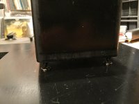
So this is the story of my eventual journey “down the rabbit hole” so to speak with my turntable. I’m sitting back again now and finally enjoying music after over 9 months of not being able to spin vinyl. I won’t be able to post all the pictures and descriptions at one time, but I will try to keep adding info and more pics. Every story has to have a beginning, so I’m gonna kick the thread off with a picture of my HW19 pretty much as she sat for about 12 years.
When I decided I wanted to pull my record collection back out after many years of storage, I didn’t know what to do about trying to put together a decent quality playback system. All I had in my possession was a cheap generic Technics turntable that didn’t work anymore. After a lot of hours researching and reading on the net I ended up with an old used HW19 MK2 off of eBay.
There were a few things wrong with the HW19. Some bits were missing from the spring suspension and of course there was no tonearm and an unusable tone arm board, but all and all it was in decent condition.
I fixed the suspension and fabricated a plywood tonearm board for it. I also fixed one of the corners of the plinth that I noticed had separated a little.
I found an affordable rewired Rega RB250 on Audiogon, mounted it with a Clearaudio Virtuoso I got on sale and was off to the races.
Almost immediately after the table was playing, I found one of the early VPI speed controllers cheap and added that to the table. I verified speed with a inexpensive hand held digital strobe I found online.
A 16.5 record cleaner showed up as a Xmas present along with some new vinyl that year.
Life was good. I was very happy with the table and enjoying my vinyl collection more than ever. I used it with an Audible Illusions 2D preamp, Counterpoint SA12 amp and my old KEF 104/2 speakers.
Of course this wasn’t actually as easy as it sounds. The cost of all this equipment added up, and I had been sucked back into a culture that wasn’t very different from what I had spent many previous years doing...building, modifying and racing cars.
So this is the story of my eventual journey “down the rabbit hole” so to speak with my turntable. I’m sitting back again now and finally enjoying music after over 9 months of not being able to spin vinyl. I won’t be able to post all the pictures and descriptions at one time, but I will try to keep adding info and more pics. Every story has to have a beginning, so I’m gonna kick the thread off with a picture of my HW19 pretty much as she sat for about 12 years.
Attachments

Too much is never enough. When it comes to audio mods for your turntable, Harry Weisfeld of VPI was more than happy to oblige. I spent as many hours obsessing over upgrades for my turntable as I did playing records. I became overly aware of what the later iterations of the HW19 and other VPI models had going for them over my table and the toys for it that were available to lust after like the SAMA motor pod, SDS speed controller and Super Platter.
My enjoyment of my records and system kept my modification urges at bay for some time. Also, the expense of modifications was prohibitive for me at the time. I have a very systematic (a.k.a OCD) manner of doing things. If all the planets were not aligned and I wasn’t going to be able to carry out all the modification ideas I had for the table at one time, then I wasn’t going to start taking it apart.
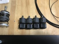
I collected a few affordable items with plans to try and improve the table at some point. I purchased the solid rubber mounts VPI sold as replacements for the spring suspension and put them away for when I was inspired to finally work on the table.
Eventually, I also found an Aries platter for sale at a great price. Unfortunately, the Aries platter didn’t come with a bearing and didn’t work with my existing bearing. This led to my first conversation with Harry over the phone. He said he didn’t have a bearing readily available to use the Aries platter on my HW19, and instead offered to allow me to trade the Aries platter in toward the recently released Super Platter with a bearing and everything I would need to use it on my HW19. It was too much to resist the offer. I ended up with the Super Platter.
Still, I didn’t tear into the HW19. Life and other projects seemed to always get in the way.
After a while I started having issues with chatter coming from the turntable motor. I managed to clean and lubricate it’s upper bushing and quite it back down. I found and bought a used Hurst motor from someone who had upgraded their table’s motor and put it away in case my motor became unusable.
At one point my daughter got hold of some citrus cleaner in a spray bottle and decided to help me clean the living room. The cleaner got on the turntable’s plinth and etched into the finish. I touched it up with some wax and buffed it out with a little success, but otherwise kept using it as it was. I suppose having to stare at the flawed finish on the turntable every time I sat down to listen to a record probably guaranteed I would eventually tear it apart.
When I finally reached that day, this is what the dining room table looked like.
My enjoyment of my records and system kept my modification urges at bay for some time. Also, the expense of modifications was prohibitive for me at the time. I have a very systematic (a.k.a OCD) manner of doing things. If all the planets were not aligned and I wasn’t going to be able to carry out all the modification ideas I had for the table at one time, then I wasn’t going to start taking it apart.
I collected a few affordable items with plans to try and improve the table at some point. I purchased the solid rubber mounts VPI sold as replacements for the spring suspension and put them away for when I was inspired to finally work on the table.
Eventually, I also found an Aries platter for sale at a great price. Unfortunately, the Aries platter didn’t come with a bearing and didn’t work with my existing bearing. This led to my first conversation with Harry over the phone. He said he didn’t have a bearing readily available to use the Aries platter on my HW19, and instead offered to allow me to trade the Aries platter in toward the recently released Super Platter with a bearing and everything I would need to use it on my HW19. It was too much to resist the offer. I ended up with the Super Platter.
Still, I didn’t tear into the HW19. Life and other projects seemed to always get in the way.
After a while I started having issues with chatter coming from the turntable motor. I managed to clean and lubricate it’s upper bushing and quite it back down. I found and bought a used Hurst motor from someone who had upgraded their table’s motor and put it away in case my motor became unusable.
At one point my daughter got hold of some citrus cleaner in a spray bottle and decided to help me clean the living room. The cleaner got on the turntable’s plinth and etched into the finish. I touched it up with some wax and buffed it out with a little success, but otherwise kept using it as it was. I suppose having to stare at the flawed finish on the turntable every time I sat down to listen to a record probably guaranteed I would eventually tear it apart.
When I finally reached that day, this is what the dining room table looked like.
Attachments

I had to start somewhere. When I stepped back and took it all in, the plinth stuck out like a sore thumb.
I never liked the awkward way it sat on the cone feet it came with. I never liked the impossible leveling process of the suspension. I didn’t like the strange way the bottom was cut way around the perimeter. Also, it needed to be re-finished as I mentioned previously.
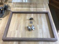
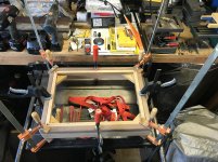
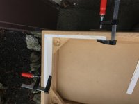
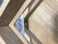
I started by sanding it down. At the same time I was trying to formulate a better leveling system. It took a little while to come up with something, and even longer to execute through trial and error. In the mean time I decided along with the sanding that I would address the other aesthetic issue of the lower edge of the plinth that I didn’t like. I cut, mitered and shaped a frame I could add to the bottom edge out of some Walnut I had.
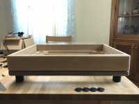
Here’s a few pics of that process and the result. I added some large rubber feet I had to test out how I thought they would look and function.
I never liked the awkward way it sat on the cone feet it came with. I never liked the impossible leveling process of the suspension. I didn’t like the strange way the bottom was cut way around the perimeter. Also, it needed to be re-finished as I mentioned previously.
I started by sanding it down. At the same time I was trying to formulate a better leveling system. It took a little while to come up with something, and even longer to execute through trial and error. In the mean time I decided along with the sanding that I would address the other aesthetic issue of the lower edge of the plinth that I didn’t like. I cut, mitered and shaped a frame I could add to the bottom edge out of some Walnut I had.
Here’s a few pics of that process and the result. I added some large rubber feet I had to test out how I thought they would look and function.
Attachments
With the simpler aspects relating to the plinth aesthetics addressed, I knew I had to move on to solving other design issues that were related to modifications or features I wanted to apply to the table. I left any finish on the wood base until later.
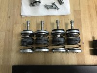
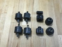
I knew I wanted to try replacing the spring suspension with the solid rubber suspension bushings that I had bought from VPI. In hindsight, I realize that I probably should have just gone to Home Despot or looked in a commercial catalog like Grainger to source these bushings. When I ordered them I thought they might be cast with some sort of compound similar to Sorbothane. They aren’t. They’re just a standard medium density motor mount style bushing with 1/4-20 threaded ends.
The additional problem I wanted to solve that related to the suspension was the fact that I never liked having to deal with the leveling process the suspension required.
In theory, the leveling shouldn’t be a big deal since you would think you only have to do it once. In practice that is not true. This is especially evident with the original spring suspension because it always seemed to resettle after trying to level it.
Initially, I had removed the plinth from the base each time I made an adjustment of the springs from the top. It got tedious very quickly. Soon after, I decided to change the hardware on the spring suspension so it could be adjusted from underneath the table with an Allen wrench. Even then, I had to lift the table up slightly or try and jam my hand in underneath to adjust one corner or another to try to get it level. It never seemed to be quite right and I was left trying to do final adjustments with the cone feet which I already didn’t like because of their awkward appearance.
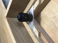
What I wanted was a way to level the table entirely from the top without having to remove the plinth, lift the table or struggle to get at adjustment points. I assumed the bushing suspension would be more stable and stay pretty much in place after it initially settled, but I wanted it to be easy to re-adjust if necessary.
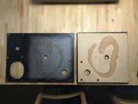
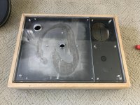
This problem was compounded by the fact that I also intended to replace the 1/2” thick MDF top surface of the plinth with a 3/4” thick piece of salvaged acrylic I had that was similar to what was used on the HW19 MK3 and beyond. That would require changing the height that the suspension mounted to the frame at in order to keep the plinth at a reasonable level with the frame. This problem required a lot of work and changes along the way to get a good result.
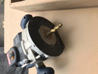
Here are some pictures of various elements and stages of the process. They show the different suspension bits. The roughed out new acrylic plinth top. My set up for hogging out the original base suspension mounts. How I rebuilt the mounting points with aluminum and some of the work on the mounts themselves which I modified so they could be adjusted from the top of the table through access holes I drilled through the entire plinth assembly.
Again, in hindsight it probably would have been easier to start from scratch and build a new wood base. I guess I was attached to this one after having gotten the aesthetics where I like them.
I knew I wanted to try replacing the spring suspension with the solid rubber suspension bushings that I had bought from VPI. In hindsight, I realize that I probably should have just gone to Home Despot or looked in a commercial catalog like Grainger to source these bushings. When I ordered them I thought they might be cast with some sort of compound similar to Sorbothane. They aren’t. They’re just a standard medium density motor mount style bushing with 1/4-20 threaded ends.
The additional problem I wanted to solve that related to the suspension was the fact that I never liked having to deal with the leveling process the suspension required.
In theory, the leveling shouldn’t be a big deal since you would think you only have to do it once. In practice that is not true. This is especially evident with the original spring suspension because it always seemed to resettle after trying to level it.
Initially, I had removed the plinth from the base each time I made an adjustment of the springs from the top. It got tedious very quickly. Soon after, I decided to change the hardware on the spring suspension so it could be adjusted from underneath the table with an Allen wrench. Even then, I had to lift the table up slightly or try and jam my hand in underneath to adjust one corner or another to try to get it level. It never seemed to be quite right and I was left trying to do final adjustments with the cone feet which I already didn’t like because of their awkward appearance.
What I wanted was a way to level the table entirely from the top without having to remove the plinth, lift the table or struggle to get at adjustment points. I assumed the bushing suspension would be more stable and stay pretty much in place after it initially settled, but I wanted it to be easy to re-adjust if necessary.
This problem was compounded by the fact that I also intended to replace the 1/2” thick MDF top surface of the plinth with a 3/4” thick piece of salvaged acrylic I had that was similar to what was used on the HW19 MK3 and beyond. That would require changing the height that the suspension mounted to the frame at in order to keep the plinth at a reasonable level with the frame. This problem required a lot of work and changes along the way to get a good result.
Here are some pictures of various elements and stages of the process. They show the different suspension bits. The roughed out new acrylic plinth top. My set up for hogging out the original base suspension mounts. How I rebuilt the mounting points with aluminum and some of the work on the mounts themselves which I modified so they could be adjusted from the top of the table through access holes I drilled through the entire plinth assembly.
Again, in hindsight it probably would have been easier to start from scratch and build a new wood base. I guess I was attached to this one after having gotten the aesthetics where I like them.
Attachments
-
 7A6A6806-6059-44CF-ACD5-5591415EA9BD.jpg984 KB · Views: 496
 -
 013E208C-5050-4533-86F2-3865AA41ED77.jpg980.5 KB · Views: 655
 -
 4384F063-784F-4D8B-90EC-E29E81FF8881.jpg957.9 KB · Views: 445
 -
 92316434-BBE7-4911-A05E-E0948D52BE30.jpg844.4 KB · Views: 413
 -
 4B126FD8-19C5-4A6C-B5D3-DCE9825ADD92.jpg593.6 KB · Views: 448
 -
 6900BF3A-8072-48BB-BE98-42C4AB0C398F.jpg1 MB · Views: 429
 -
 0516B09A-5F61-407B-BD01-080622E9494B.jpg735.5 KB · Views: 414
 -
 188BCD5F-EF3F-408D-9603-4D071A5DAFE7.jpg918.6 KB · Views: 435
 -
 192ACE70-1E1F-482C-ADB8-3EE12AA36DF9.jpg992.6 KB · Views: 428
 -
 2E1A31FA-F2D5-45D3-B376-B2E4C3C2EFA0.jpg883 KB · Views: 467
Last edited:
Personally, I don't like spring feet. I had VPI table. Here was what I did for VPI. It was vast improvement for the stock table. However, there was one draw back. The bicycle inner tire couldn't held pressure for long time. I would suggest to use hand balls where the inner tire was.
Attachments
Thanks for the comments.
@Super...The original spring suspension is gone and in its place are rubber mounts. I’m not sure if you consider the rubber mounts that I modified for adjustable leveling as still being “springs”. They most definitely would retain some level of flexibility, albeit very little based on the durometer of their rubber. I choose not to go with a completely solid suspension in order to retain some small level of damping.
I am just presenting documentation here of decisions I already made and carried out on this project that is now together and running.
I will say that a decision I made to integrate a motor system on this table that would allow me to drive the table via belt or rim methods has led me to the conclusion that I will have to construct some kind of damping platform for the entire table to sit on.
My table sits on an IKEA bookcase that is hung on the wall right now. When I experimented with the rim drive the bookcase became an amplifier for any vibration that was transmitted down through the motor. I like your solution for a damping platform and I do in fact already have a bunch of blue handballs that were for experimenting with such a platform design. I haven’t decided yet what the solution would be for the rim drive, but I will be building a new room to listen in soon and things will probably change quite a bit.
Some comments after a quick skim (will try to read more carefully in a bit):
1) Many people have found Herbie's Big Tall Tenderfeet to be an improvement over the stock HW-19 suspension. I've used a number of Herbie's products, including Tenderfeet, and they're excellent. Not cheap, but not obscene either. Also worth using extra thick grungebusters between the motor and plinth.
2) If you're using a Rega mount, look into an Audiomods tonearm. They're very reasonably priced given the current GBP to USD exchange rate, and a nice improvement over stock Rega arms. I'm using an older Audiomods Classic on my Scout Jr. and it handily outperforms the Player arm, if not as sturdy in the hand. Not cheap, but definitely worthwhile.
That's all for now. Looks like a fun project!
In my opinions, a good turntable stand must have two elements. Mass and damping. In my design, the weight of sand box is mass. Sand and air tube act as damping devices. A while ago, I bought some industrial air bladders from ebay. I don’t use them now but if one day, I need to make another stand, I will use them with a low pressure air pump and to use an air regulator to keep constant air pressure of air bladders. If I want to damp different frequency, I can change different air pressure. I think it will work wonderfully.
Attachments
...The bicycle inner tire couldn't held pressure for long time....
Tighten, or replace, the valve. (To verify first: smear thick soapy water on the stem end and wait hours for a bubble.)
Also for this job, consider asking a high-class bicycle shop about premium tubes. You don't need "thorn resistant", but you do not want the low-bid rubber in generic bike tubes.
This project was spread out over a long period of time and there were several aspects to it that often overlapped. I am usually very systematic about how I go through a project.
Since the topic of damping has come up, and it is something I definitely spent time and resources trying to address I might as well talk a little about how what my thoughts were relating to it.
There is a mountain of writing, talk and marketing about damping relating to turntables. One of the big buzz phrases to erupt onto the scene over the last several years was “constrained layer damping”.
I spent a bit of time reading whatever articles, threads and white papers that I could about damping. Although constrained layer damping seems to be all the rage, it seems like very little of what is on the market or being made fits a true definition of CLD. I actually found some very interesting articles and white papers on the subject of granular damping. It is nothing really new, but it seems to work. I decided to try and simplify my approach to damping the table as much as possible, but used more than one method.
Everyone likes pictures. I added as many decent ones in this and the next post that I could find of the plinth and base as I was trying to resolve both of them, their damping and getting them to work together with the new suspension design I came up with.
As the plinth progressed I decided I would take the approach of laminating a damping layer (or layers) between the original steel sub-plinth and the new 3/4” acrylic upper layer. Although VPI had simply used the steel/acrylic by itself, and it was generally viewed as an improvement over the MK2 steel/MDF combination, neither material had any very desirable damping factor by themselves or in combination.
I was working with what I had on hand, and I happened to have some old lead sheet I had scavenged years ago from my grandfathers basement. I already knew the lead was a good damping material. I laid out a template that matched the steel sub-plinth and cut the lead carefully with rubber gloves and a respirator.
I didn’t like the idea of the lead being exposed in any way, so I bought a can of paintable liquid rubber at Walmart and sealed the sheet of lead with a few coats entirely to encase it. I had used an old rolling pin to flatten out the lead on the top of my cast iron table saw. It was not perfectly flat to begin with and the rubber dried with a slight texture even though I used the smoothest roller I could find. I hoped it would flatten out from the pressure of the extra screws I had added to hold the steel and acrylic together. The texture showed through the acrylic top even after I had wet sanded it to create a uniform grain-like finish on it.
I decided to add a layer of quality black drawing paper on the top and bottom of the rubber encased lead sheet to prevent the texture from showing through and to act as a sort of gasket that would help smooth out any irregularities and allow me to disassemble the plinth to try other damping materials if I wished.
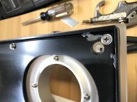
As I was working on the issue of the damping of the plinth, I was also addressing what I needed to do to have a flexible tonearm mounting point that would allow for the arm to be mounted at the correct height for the new thicker platter and also make it easier to build different arm boards and swap them out easily in order to try different arms.
Another detail that missed my attention at first was that the screws at the corners of the plinth holding the arm board acrylic in place interfered with the suspension bushings that the steel plate sits on. The holes had to be counter sunk and appropriate hardware used.
Since the topic of damping has come up, and it is something I definitely spent time and resources trying to address I might as well talk a little about how what my thoughts were relating to it.
There is a mountain of writing, talk and marketing about damping relating to turntables. One of the big buzz phrases to erupt onto the scene over the last several years was “constrained layer damping”.
I spent a bit of time reading whatever articles, threads and white papers that I could about damping. Although constrained layer damping seems to be all the rage, it seems like very little of what is on the market or being made fits a true definition of CLD. I actually found some very interesting articles and white papers on the subject of granular damping. It is nothing really new, but it seems to work. I decided to try and simplify my approach to damping the table as much as possible, but used more than one method.
Everyone likes pictures. I added as many decent ones in this and the next post that I could find of the plinth and base as I was trying to resolve both of them, their damping and getting them to work together with the new suspension design I came up with.
As the plinth progressed I decided I would take the approach of laminating a damping layer (or layers) between the original steel sub-plinth and the new 3/4” acrylic upper layer. Although VPI had simply used the steel/acrylic by itself, and it was generally viewed as an improvement over the MK2 steel/MDF combination, neither material had any very desirable damping factor by themselves or in combination.
I was working with what I had on hand, and I happened to have some old lead sheet I had scavenged years ago from my grandfathers basement. I already knew the lead was a good damping material. I laid out a template that matched the steel sub-plinth and cut the lead carefully with rubber gloves and a respirator.
I didn’t like the idea of the lead being exposed in any way, so I bought a can of paintable liquid rubber at Walmart and sealed the sheet of lead with a few coats entirely to encase it. I had used an old rolling pin to flatten out the lead on the top of my cast iron table saw. It was not perfectly flat to begin with and the rubber dried with a slight texture even though I used the smoothest roller I could find. I hoped it would flatten out from the pressure of the extra screws I had added to hold the steel and acrylic together. The texture showed through the acrylic top even after I had wet sanded it to create a uniform grain-like finish on it.
I decided to add a layer of quality black drawing paper on the top and bottom of the rubber encased lead sheet to prevent the texture from showing through and to act as a sort of gasket that would help smooth out any irregularities and allow me to disassemble the plinth to try other damping materials if I wished.
As I was working on the issue of the damping of the plinth, I was also addressing what I needed to do to have a flexible tonearm mounting point that would allow for the arm to be mounted at the correct height for the new thicker platter and also make it easier to build different arm boards and swap them out easily in order to try different arms.
Another detail that missed my attention at first was that the screws at the corners of the plinth holding the arm board acrylic in place interfered with the suspension bushings that the steel plate sits on. The holes had to be counter sunk and appropriate hardware used.
Attachments
-
 3EDB4E8A-F2B0-4808-9D99-C3DDA5709930.jpg941.7 KB · Views: 492
 -
 7C051596-3EA6-4DB4-8C5B-FC6ABBCF4165.jpg933.7 KB · Views: 487
 -
 16A551F9-F188-418E-B76D-D90AC925B2E5.jpg700.8 KB · Views: 495
 -
 48970378-A28F-4244-874C-8795F8071645.jpg608.7 KB · Views: 486
 -
 36F4B159-C613-4AEC-9FE6-8C56C71B89E3.jpg897.1 KB · Views: 475
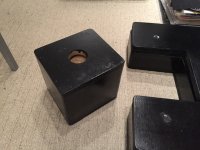
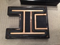
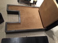
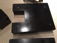
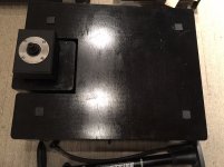
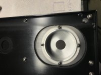
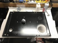
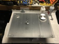
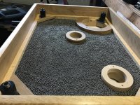
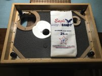
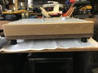
After considering what to do about damping the base for a while I decided to build a well inside it that would allow me to fill it with lead shot in order to add mass and have the benefit of granular damping.
The bottom of the well is made from MDF to fit tightly in from underneath and held in place with pocket screws around the perimeter. I made circular openings to accommodate the stand alone motor pod I would be using along with clearance holes for the main bearing and tonearm wiring. The perimeter of the openings were doubled up with more MDF and some blocks added to the corners to allow a sheet of acrylic to be formed into a cover that would seal the compartment that held the lead shot.
I got a little rediculous and even added a tiny compartment of lead shot underneath the one isolated suspension point behind the motor pod opening.
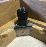
I also decided to add a thin sorbathane layer at the mounting point of the new rubber feet that is compressed like a sandwich between the top of the feet and a fender washer butted against the bottom of the base.
The bottom of the well is made from MDF to fit tightly in from underneath and held in place with pocket screws around the perimeter. I made circular openings to accommodate the stand alone motor pod I would be using along with clearance holes for the main bearing and tonearm wiring. The perimeter of the openings were doubled up with more MDF and some blocks added to the corners to allow a sheet of acrylic to be formed into a cover that would seal the compartment that held the lead shot.
I got a little rediculous and even added a tiny compartment of lead shot underneath the one isolated suspension point behind the motor pod opening.
I also decided to add a thin sorbathane layer at the mounting point of the new rubber feet that is compressed like a sandwich between the top of the feet and a fender washer butted against the bottom of the base.
Attachments
-
 BBA35B37-0123-4EDF-AA3A-59154C3AEB49.jpg1.1 MB · Views: 369
 -
 DFA51244-52C4-453B-8BBB-891DE44CFE40.jpg1 MB · Views: 345
 -
 5E7CECEB-8D1E-449C-BDBA-A9F7E460E18B.jpg765 KB · Views: 362
 -
 F9D95B52-B403-4D7D-A427-2C11CA6049CC.jpg599.1 KB · Views: 369
 -
 37B9EC66-7980-4B10-B12B-652973E21D91.jpg934.9 KB · Views: 375
Are you listening to the deck in between different tweaks to see what each one does?
If you asked me that question, my answer is yes. For my VPI stand I posted in this thread, I simply listened to the table with and without the stand. There was difference sonically for VPI, but not too much for SME 20 table. I think it is because SME 20 has nice suspension system in place already. VPI does need some kind of anti vibration device.
Was more directed at chromenuts, but yeah. I try to be careful with familiarizing myself with each tweak separately, so that I know which one to abandon if I don't like it. Like when I tried a baggie of playground sand in my motor pod, or brass weights on top of it. Horrible results in both cases. But damping the casing with thin grungebuster scraps between the plates? That worked great.If you asked me that question, my answer is yes. For my VPI stand I posted in this thread, I simply listened to the table with and without the stand. There was difference sonically for VPI, but not too much for SME 20 table. I think it is because SME 20 has nice suspension system in place already. VPI does need some kind of anti vibration device.
It wasn’t realistic to make this a tweak as I went project. There were too many aspects of the table that needed to be addressed or changed once I made the decision to dive into it.
Prior to starting the project I had committed to replacing the original platter with a super platter which is four times heavier and twice as thick as stock.
The platter change required modifications to the plinth in order for me to be able to set a tonearm up properly. Since I had to replace part of it and figure out a way to compensate for the new platter height I figured it should all be replaced and I should apply whatever improvements that seemed worth while.
There was no way the stock suspension could support the new platter and heavier plinth properly, so the suspension had to be changed before I could use the table.
The same applied to my drive system which was already having issues. I knew the 25lb platter would just make them worse. Once I committed to replacing it other aspects of the table had to evolve as well.
As I mentioned before there was more than one time that I thought to myself I should have just started building a new table from scratch.
I had actually considered building something that would mimic an Avenger style table. I had the materials on hand and I may still do it.
I guess I was more interested in the challenge of trying to take this table in its simple traditional form factor and implementing what I thought would be comprehensive improvements to all of its elements much like I felt Harry was trying to do when he released the Classic series of tables.
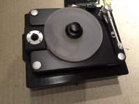
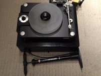
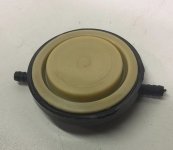
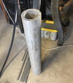
I’m kind of tired tonight, so I’ll just leave you with a teaser of one of the more involved parts of the project which was building a new drive system. Here’s a pic of what I started with.
Prior to starting the project I had committed to replacing the original platter with a super platter which is four times heavier and twice as thick as stock.
The platter change required modifications to the plinth in order for me to be able to set a tonearm up properly. Since I had to replace part of it and figure out a way to compensate for the new platter height I figured it should all be replaced and I should apply whatever improvements that seemed worth while.
There was no way the stock suspension could support the new platter and heavier plinth properly, so the suspension had to be changed before I could use the table.
The same applied to my drive system which was already having issues. I knew the 25lb platter would just make them worse. Once I committed to replacing it other aspects of the table had to evolve as well.
As I mentioned before there was more than one time that I thought to myself I should have just started building a new table from scratch.
I had actually considered building something that would mimic an Avenger style table. I had the materials on hand and I may still do it.
I guess I was more interested in the challenge of trying to take this table in its simple traditional form factor and implementing what I thought would be comprehensive improvements to all of its elements much like I felt Harry was trying to do when he released the Classic series of tables.
I’m kind of tired tonight, so I’ll just leave you with a teaser of one of the more involved parts of the project which was building a new drive system. Here’s a pic of what I started with.
Attachments
Over the years I owned the HW19 I read various criticism about it’s drive system. I noted the progression of drive system offerings from VPI with changes to motor speed and power ratings, stand alone units, the addition of flywheels, multiple motors and rim drives. However, they essentially kept using the same Hurst motors which was often the focus of criticism. To this day they still appear to be using the same Hurst motors even on their $30,000 tables.
VPI’s SDS motor control system seemed to have mixed reviews depending on who was writing about it. The earlier controller I had was almost scoffed at. One person stated in a thread that it was “little more than a power inverter like those used in automobiles”. I suppose it served its purpose and it was better than having nothing to control motor speed.
When I became aware of Phoenix Engineering and their Falcon controller along with the Roadrunner tachometer I made up my mind after reading about it and it’s reviews that it would be the direction I would go when I had the money and was ready to dive into the table. Unfortunately, I waited too long. By the time I thought I could afford them production had stopped. However, after a period of time I found a pair for sale on the used market. I had the funds and snatched them up.
By the time I got my hands on the Phoenix controller and had started seriously considering how I was going to proceed I had decided I wanted a stand alone motor. The HW19 SAMA that VPI produced was just plain ugly, used the same Hurst motor, was hard to find and overpriced in my eyes. As I mentioned before, I had started fantasizing about the possibility of taking the parts I had acquired and trying to build something more exotic from scratch like a TNT or Avenger style table.
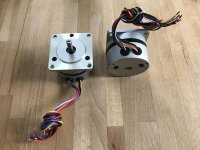
At about that time I came across a VPI single motor flywheel unit on eBay for a reasonable price. I thought that if I could figure out how to integrate it into my project that I would be saved from a lot of time and grief in building my own stand alone motor. I hoped it would be a good solution and I bought it. This decision became an immediate failure on my part. Unfortunately, I was not aware that the flywheel unit utilized one of the Hurst 300 RPM 7.5 Watt motors. The Falcon controller I had already bought was only able to support the Hurst 600 RPM 5.5 Watt or similar motors.
While trying to figure out what I was going to do, I conversed with the seller I had acquired the Pheonix controller from. He informed me that the Pheonix designer was active on DIYAudio and that there was a possibility of modifying the controller and adding an amplifier to it so that it could drive motors with higher power ratings.
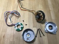
Little did I know, the Pheonix designer had already begun development of a DIY turntable drive project here on the forums. It is the 4 phase sine wave generator which can be used with various amplifiers and/or transformers to drive a large variety of turntable motors. Eventually he also released the design for a 3 channel class D amplifier designed to work with a specific 3 phase BLDC motor that required no transformers. The project is supported through the Oshpark prototyping PCB service and a shared cart at Mouser with the designers excellent support and enormous generosity. This was the missing piece to my puzzle and ultimately what pushed me to finally dive into this project.
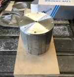
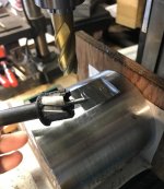
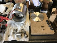
Like the other phases of this project the drive system had many aspects that I worked on consecutively in order to achieve a satisfactory result. I first had to source the new motor along with the PCBs and all the required components. That was made much easier because of all the work that had been put into the project by its designer.
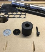
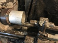
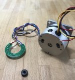
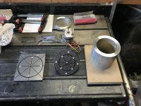
I started with fabrication of the motor pod. I had to modify the BLDC motor for use with the new controller by removing the hall sensor it is manufactured with. The pod and especially the umbilical connection went through several changes due to clearance issues I had created by adding the well full of lead shot to the base of the table.
VPI’s SDS motor control system seemed to have mixed reviews depending on who was writing about it. The earlier controller I had was almost scoffed at. One person stated in a thread that it was “little more than a power inverter like those used in automobiles”. I suppose it served its purpose and it was better than having nothing to control motor speed.
When I became aware of Phoenix Engineering and their Falcon controller along with the Roadrunner tachometer I made up my mind after reading about it and it’s reviews that it would be the direction I would go when I had the money and was ready to dive into the table. Unfortunately, I waited too long. By the time I thought I could afford them production had stopped. However, after a period of time I found a pair for sale on the used market. I had the funds and snatched them up.
By the time I got my hands on the Phoenix controller and had started seriously considering how I was going to proceed I had decided I wanted a stand alone motor. The HW19 SAMA that VPI produced was just plain ugly, used the same Hurst motor, was hard to find and overpriced in my eyes. As I mentioned before, I had started fantasizing about the possibility of taking the parts I had acquired and trying to build something more exotic from scratch like a TNT or Avenger style table.
At about that time I came across a VPI single motor flywheel unit on eBay for a reasonable price. I thought that if I could figure out how to integrate it into my project that I would be saved from a lot of time and grief in building my own stand alone motor. I hoped it would be a good solution and I bought it. This decision became an immediate failure on my part. Unfortunately, I was not aware that the flywheel unit utilized one of the Hurst 300 RPM 7.5 Watt motors. The Falcon controller I had already bought was only able to support the Hurst 600 RPM 5.5 Watt or similar motors.
While trying to figure out what I was going to do, I conversed with the seller I had acquired the Pheonix controller from. He informed me that the Pheonix designer was active on DIYAudio and that there was a possibility of modifying the controller and adding an amplifier to it so that it could drive motors with higher power ratings.
Little did I know, the Pheonix designer had already begun development of a DIY turntable drive project here on the forums. It is the 4 phase sine wave generator which can be used with various amplifiers and/or transformers to drive a large variety of turntable motors. Eventually he also released the design for a 3 channel class D amplifier designed to work with a specific 3 phase BLDC motor that required no transformers. The project is supported through the Oshpark prototyping PCB service and a shared cart at Mouser with the designers excellent support and enormous generosity. This was the missing piece to my puzzle and ultimately what pushed me to finally dive into this project.
Like the other phases of this project the drive system had many aspects that I worked on consecutively in order to achieve a satisfactory result. I first had to source the new motor along with the PCBs and all the required components. That was made much easier because of all the work that had been put into the project by its designer.
I started with fabrication of the motor pod. I had to modify the BLDC motor for use with the new controller by removing the hall sensor it is manufactured with. The pod and especially the umbilical connection went through several changes due to clearance issues I had created by adding the well full of lead shot to the base of the table.
Attachments
-
 B2200B07-DC02-4EC9-B16A-0AC6B9A76A47.jpg1,009.1 KB · Views: 369
 -
 604A83C8-8990-4A14-ABC9-CFEDCAD19CA9.jpg1 MB · Views: 325
 -
 CEDA231D-701B-4541-A873-C009E14E89B0.jpg1,002 KB · Views: 327
 -
 2F2CC646-9118-4105-A636-C52D186A5A42.jpg680.8 KB · Views: 304
 -
 092B3849-7AA8-4B1D-ACDB-58D286A15316.jpg1,002.7 KB · Views: 322
 -
 E2898BD7-99A9-42FD-8893-2D77C1F9EA5E.jpg782.8 KB · Views: 309
 -
 E253063A-F8F3-4CD1-9A2B-6E39EF88AC71.jpg928.2 KB · Views: 331
 -
 4799A6C5-8E83-4BBF-AE6A-8DA4B1A35F68.jpg506.3 KB · Views: 319
 -
 67E6F068-DAA9-4447-8521-15416EC3172B.jpg994.7 KB · Views: 373

- Home
- Source & Line
- Analogue Source
- VPI resto-mod...a tale of bastardizing my HW19