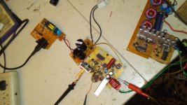
Some time ago i stumbled upon a broken DVD player which contained an interesting easy to build SMPS module. The heart of the module was the TNY288 chip which I de-soldered and after some reading of datasheets and downloading of the accompanying application found in Power integrations site, I managed to calculate and build a very easy and basic 300V 100mA power supply ideal for experimenting with tubes.
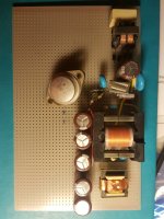
The schematic is straight forward and the construction of the transformer easy and basic. The ripple at the output at full load is less than 15mV which I believe might go even lower with some experimentation but at least it is acceptable.
Moreover, the output voltage can be lowered to any level by changing the zener at the output. For example, for 300V out we need an 100V zener, for 100v output we need a 33V zener.
Now it is about time to build the next one with bigger Chip TOP258 for a 200W 1200V SMPS to see if its going to work and perform as well as the smaller one...
Attachments

Last edited:
Very interesting, so simple. Have you tried using a separate winding for feedback so you dont need the opto?
Hi,
Very interesting. Did you model a PCB for this? Care to share it?
I'm wondering if the PC817 opto-coupler could be replaced by a venerable 6N138?
Cheers.
Very interesting. Did you model a PCB for this? Care to share it?
I'm wondering if the PC817 opto-coupler could be replaced by a venerable 6N138?
Cheers.
some measurements
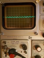
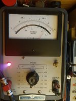
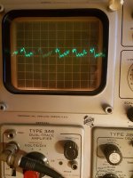
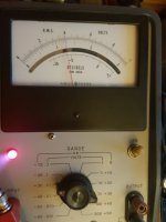
So, since it is Sunday afternoon and having some spare time, I took some measurements with my very old scope and mV meter.
So at 1 mA there is less than 1mVRMS ripple.
At 100mA (full load) there is less than 15mV RMS ripple.
All in all, to me this seems a good outcome, especially considering the simplicity of this smps, as well as the fact that this is the first try with no attempt to optimize the outcome and the filtering.
Attachments
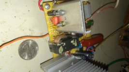
What did you do to ensure that the insulation is sufficient? I guess the capacitors C1 and C5 are X and Y types, respectively, and that you use perfboard without copper or with removed copper, but how about the DIY transformer?
Capacitors are correct types for their positions, the board is experimental perforated with copper and will eventually lead to a dedicated design with better creepage.
The insulation is 3 turns of 0.1mm mylar film between primary and secondary.
Between secondaries 2 turns of 0.1mm mylar film and all this impregnated (not vacuum) in polyurethane varnish.
The insulation is 3 turns of 0.1mm mylar film between primary and secondary.
Between secondaries 2 turns of 0.1mm mylar film and all this impregnated (not vacuum) in polyurethane varnish.
Panos29, thanks for this info. I had never heard of these chips or Power Integration, so I spent several hours playing with their design tools and came up with a paper design. I'll get the parts on my next Mouser order and see if it goes, or blows. All of my previous off line experiments ended rather quickly with flaming plastic and burnt parts.
I chose the TOP261EN part and I'm aiming for 450 volts at 1/2 amp.
I chose the TOP261EN part and I'm aiming for 450 volts at 1/2 amp.

Isolation transformer, also can use lower voltage, and a light bulb in series as initial power up takes place I find usually helps in preventing flaming plastic and melted copper. 🙂
🙂
Not to say I haven't fried plenty of parts myself, welcome to SMPS.....ha!
🙂Not to say I haven't fried plenty of parts myself, welcome to SMPS.....ha!
Panos29, thanks for this info. I had never heard of these chips or Power Integration, so I spent several hours playing with their design tools and came up with a paper design. I'll get the parts on my next Mouser order and see if it goes, or blows. All of my previous off line experiments ended rather quickly with flaming plastic and burnt parts.
I chose the TOP261EN part and I'm aiming for 450 volts at 1/2 amp.
TOP261 is nice and powerful but it only does 66khz instead of 132knz that some other do, meaning you are going to need bigger magnetics. I would choose some other option for higher frequency.
TOP261 is nice and powerful but it only does 66khz instead of 132knz that some other do
The TOP261YN is fixed at 66 KHz because of the extra ground pin that replaced the frequency pin. The TOP261EN has the capability of switching frequencies, and my simulation was done at 132 KHz.
I ran dozens of sims on their web based PI Expert simulator trying to find a sim that met my power requirements with off the shelf magnetics that I could order in small quantities. This is the first sim that met the requirements, so I'll spend a few bucks to test it. There will likely be more.
Their simulator has a maximum output voltage limit of 100 volts. I need a bit more than that so I picked 100 volts at 2.25 amps, same 225 watts. Of course their transformer winding info is now wrong, and my secondary will make the leakage inductance different from the sim, but I need to start somewhere.
Isolation transformer, also can use lower voltage, and a light bulb in series as initial power up takes place
I haven't connected silicon directly to the wall outlet or to a car battery in a long time. Back then I placed inverted coffee mugs over the mosfets to avoid being hit by exploding shrapnel. Now, I plan to replace the line rectifier with a DC power supply that has current limiting capability. No direct connection to the line voltage until all is working on a current limited power supply.
I do have a BIG isolation transformer and several different wattage light bulbs for use if I get that far before blowing up too much cash! I no longer work for Motorola, so I no longer get free mosfets. Motorola quit making silicon long ago, but the local ON Semi rep brought me free stuff almost weekly. So did the Freescale, National and Microchip people.
I will get some spare chips......just in case!
It is good Tactic that you have chosen to use higher frequency alternative.
About the 100v limited application, you can use multiple 100v secondaries connected in series as in my example, you can use 4 or 5 secondaries in series. This way you will stress the rectifiers even less, otherwise you will possibly need to series connect 2 or more rectifiers.
Just for your info, when I connected the secondaries in series and used one rectifier only, for some reason it did not worked right. Also if you use too much capacitance at the output it will not start.
Had that happen once. Much more careful now.I haven't connected silicon directly to the wall outlet or to a car battery in a long time. Back then I placed inverted coffee mugs over the mosfets to avoid being hit by exploding shrapnel.
 There is something about a gate drive transformer that I like.😀.
 I finally did get to the step of connecting directly to wall outlet in this small experimental converter. Output for 12VDC like a car supply from 120VAC. Asynchronous half bridge. Transformer a bit undersized, but it is what I had scrapped out of some old broken junk. Ha!
Attachments
What is the purpose of C5?
Cheers
Ian
It is used to prevent or reduce primary to secondary differential mode noise interfering with the feedback loop.
Ideally it should be placed between/across the 'ground' nodes of the opto-isolator.
For safety purposes it should also be a Class Y capacitor.
The given circuit does not show as such but the value of 220pF might be indicative of its nature... it will be a blue ceramic disc capacitor.
You may also see examples where that particular component has an RC network in parallel with it in order to damp ringing.
The circuit in this thread does not itself make reference to mains/chassis ground so you would have to assume that it is Class II, double insulated.
You might see that there is a bit of a dilemma, here and elsewhere, in terms of input and overall filtering in respect of Class II.
SMPS grounding
https://www.hypex.nl/documenten/download/878
Picture Attached. C21/C22/C79/C80 and C81.
In particular C21 and C22 are part of the input filter and act in conjunction with TR3 and TR4 which are Common Mode Chokes to filter Ground noise.
C79 and C81 are the equivalent of C5 in this thread.
However it is a bit of a problem when you have a Double Insulated, Class II, supply with, supposedly, no reference to mains earth.
In this case Hypex has tied them to secondary ground which at face value seems, is probably, slightly wrong. At a simple level it does make sense to direct input noise into the output of your power supply.
The circuit in this thread includes a similar input filter but omits the Class Y capacitors... no mains earth. C1 is a Class X2 device and, in conjunction with uncoupled inductance in L1, filters differential, Live to Neutral, noise.
Leakage inductance in common mode chokes is small but you get to use big Class X2 capacitors.
Common mode inductors have big Common Mode values because the Live/Neutral currents cancel and that lets you use small Class Y capacitors.
You are forced to do this because they represent a source of or path for Earth Leakage, people killing, currents. Probably not as important as tripping earth leakage circuit breakers.
Of course if you design for Class II, double insulated, then you do not need to test, in regulatory terms, for Common Mode, Ground, noise... there is no Ground.
I suppose that works if you have some problems getting your supply to pass the relevant standards.
However if you include components to nominally, incorrectly or otherwise, deal with such cases you are, in effect, offloading the responsibility onto the end user.
The given circuit does not show as such but the value of 220pF might be indicative of its nature... it will be a blue ceramic disc capacitor.
That circuit is the output from the Power Integrations (chip manufacturer) simulator. It does not cover specific safety requirements, just the general case. The type of cap (Y cap) is given in the BOM output from the simulator. Many of the specific components listed in the simulator output are no longer in production.
- Status
- Not open for further replies.
- Home
- Amplifiers
- Power Supplies
- DIY Off-Line SMPS 300V @ 100ma experiment