If you adjust the bias current and/or rail voltages of the Aleph, you will also
need to adjust the DC offset at the output.
as written in post #18
again ,ZM doing all the heavy work ......
Attachments
...I get my first electricity bill....O-U-C-H!!!...
Ah, but your heating-oil bill is slightly down, no?
For "I work from home and have my system on all day" but not at FULL VOLUME, a smaller amp would be appropriate. Maybe this amp with, as said, half rail voltage (with due concern for keeping everything happy and suitable bias). Half voltage, half current, 6dB down, and 1/4 the electric bill.
Ah, but your heating-oil bill is slightly down, no?
For me it works great. Electric heat - municipal power company with rates among the lowest in MA. It's the perfect winter trade off. No guilt running the Aleph 5.
The summers are a killer!
Do you know about how effecent your speakers are and what power peaks you are hitting when you are just using them for casual listening ? Might not a cheap ACA be all you need for just your casual background listening ?
If I may ask? How much did those line arrays cost you to make? I've always had a hankering to do something like that, and I have a bit of spare time on my hands at the moment.
If I may ask? How much did those line arrays cost you to make? I've always had a hankering to do something like that, and I have a bit of spare time on my hands at the moment.
So Far the spend has been US$ 1400/- and so worth it.
The biggest cost item was the Vifa TG9FD10-08. I paid about US$19/ea. So for 56 (I bought 6 extra) I paid ~US$ 1064/-. It compares well with with the Dayton Audio ND90-8 (except in Xmax) as recommended by the MCLA design. Also the Vifa was what was used in the IDS-25 which I have heaard and loved.
The coffins (Boxes 😀) I built out of a single sheet of 4' X 8' of 0.5" thick MDF about $35/-
Add another $250 for hardware, fill, wiring etc.(each unit ~100ft.) etc.
Lots of elbow grease $$$$$ 😀. Now I used good quality low oxygen wire from a local source but if you decide to use Cardas wire etc. this could go much higher.
So far have spent a month of time on them. Mostly weekends. Spent 10 years think about them 🙂
I have not applied a finish on them as yet. Looking to do a piano finish. May get this professionally done 😱🙄 . I did apply vinyl seal coat and have sanded them down 2 times. This is more a time and infrastructure issue (too much trouble to create a dust-free environment). Also have not designed the cover/screen as yet, but have embedded magnets for future use.
I can post some some detailed pics of the build (maybe on separate thread).......
If you adjust the bias current and/or rail voltages of the Aleph, you will also
need to adjust the DC offset at the output.
I hope to carve out some time within the next 2 weeks to at least experiment. I will post all measurements and details before and after.
cheers & thanks
Raman
If I may ask? How much did those line arrays cost you to make? I've always had a hankering to do something like that, and I have a bit of spare time on my hands at the moment.
A much cheaper alernative to the Vifa TG9FD10-08 is the Vifa TC9FD18-08 ...paper cone vs..glass fiber cone and almost 50% cheaper.
See the 2 towers project here......The making of: The Two Towers (a 25 driver Full Range line array)
I think you should build a second amp. Your Aleph 2 consumes 300 watts per side. The Aleph J uses 100 watts per side. If you want to go lower the M2 uses 80 watts per side. A mini Aleph J is probably even lower (60 watts?).
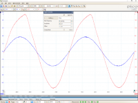
So Finally I got some time to walk one unit down to the basement (@60 lbs each this wont be happening too often I hope). Rewired the transformer primary to 240V and tested. Did not do any Bias or other adjustments. Here are the findings with 8ohm load resistor:
Before alterations:
- DC Offset ~ 11mV
- Idle current ~6.2 Amps measured across source resistors
- Rail voltage +-42V
- Gain 19.85 dB (input: 1KHz, 2V p-p)
- Frequency response clean from 10Hz through 100KHz @ 4V p-p input
After alterations to the Primary:
- DC Offset 75mV
- Idle Current ~6.3 Amps
- Rail Voltage 17.85V (Was expecting this to be at least 21V??)
- Gain 20.032 dB
- Frequency response was clean up to 2.8V p-p but started clipping at lower half of cycle at ~3V p-p input.
I can post the pics from the scope. Have not done any listening tests (too heavy to carry and cumbersome when disassembled.
Pass DIY Addict
Joined 2000
Paid Member
Your rail voltage dropped after altering your primary wiring due to the current draw - it impacted to power regulation of the transformer. Not that big of a deal at all. It's been a while since I looked at an Aleph3 schematic - is there an adjustment pot for offset? This should be an easy adjustment to make, either by inserting a pot, or by altering the value of the pot to allow more adjustment range..
Overall, a nice result: You've moved from burning 260w to about 112w each. You should be able to get a satisfying level of volume without having to push them into clipping.
Overall, a nice result: You've moved from burning 260w to about 112w each. You should be able to get a satisfying level of volume without having to push them into clipping.
Yes...thanks...looks promising....i will replace the 56k resistor with a 100k pot and do some more tests. May also carry the beast back up to do some listening tests 🙂
you can divide that DC offset between two voltage states ...... in full voltage state set to negative , hoping it'll go in half voltage state on same value , but other side of zero
Pass DIY Addict
Joined 2000
Paid Member
Ah - so with a spread of ~60mV between the configurations, aim for -30mV with one power configuration and +30mV with the opposite setting. This is better than fiddling with a pot, but will take a bit of experimentation. Very clever!
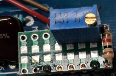
setting either with additional trimpot in input mosfet drain , or with additional trimpot in CCS above/feeding input LTP
Nice one! Glad you got to a good result. 🙂
Thanks! Your suggestion after all 🙂. Less is more.
Ran out of trimpots...but will post soon on adjustments.
I plan to offload the trimpots it the two locations as ZM suggested onto a plugable (new word 🙂) prototype board with easy access for further fine tuning.
So I did manage to salvage a 100 K ohm trimpot of an old experiment and did some tests. Basically I only replaced the 56.2 K bias resistor with a 1K R and a trimpot. Here are the results:
With Primary configured to 240V
DC offset was set to 32mV
- Idle current was 3.636A
- Gain 20 dB
- Clipping starts at 3.6V p-p input (@1KHz)
- Final result for Bias resistor was 17.83 K ohms
- Rails were measured at 18.53 V +-
With the above Bias config and primary back to 120V~:
- DC offset came out at -24mV
- Idle current was 2.5A
- Rail voltage 40.2V
- No clipping but some minor wave deformation above 15KHz
Also I noticed that the real maximum for inpu across full bandwidth is ~2.3V p-p. Anything above that shows mild wave deformation/distortion at high frequencies (>15KHz). The good thing is my hearing ceases at 14.87K 😀.
Will post pics.
I will be traveling next few days but interested in your opinions....
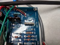
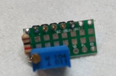
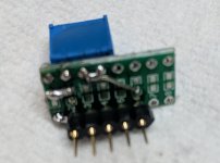


- Status
- Not open for further replies.
- Home
- Amplifiers
- Pass Labs
- Pass Aleph 2 dual power modes?
