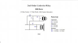
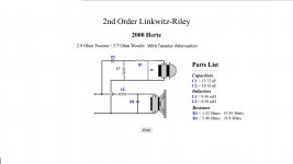
So I've come up with what I want for a 2-way crossover:
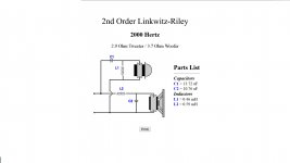
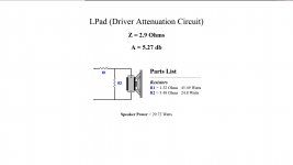
And the attenuation circuit:
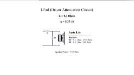
So my question is where do I place the resistors for the tweeter? Before or after the capacitor? Before or after the Coil?
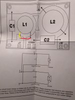
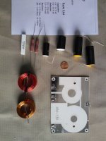
Here is the sheet that came with the PCB:
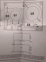
Thanks in advance for any help, it's really appreciated.
-Rob

And the attenuation circuit:

So my question is where do I place the resistors for the tweeter? Before or after the capacitor? Before or after the Coil?
Here is the sheet that came with the PCB:

Thanks in advance for any help, it's really appreciated.
-Rob
Your schematic looks good but the layout is different. I would have expected the L-pad to be hanging off the board after the tweeter out terminal, unless you rearrange it a little.
Your schematic looks good but the layout is different. I would have expected the L-pad to be hanging off the board after the tweeter out terminal, unless you rearrange it a little.
I think I understand what you're saying. After the tweeter outputs from the crossover board, then add R1 and R2 for the l-pad part? Now that I look at it again, I see my original location for R1 would have had an effect on the coil.
Would this work correctly? (R1 yellow, R2 red):
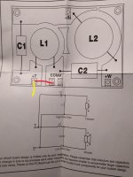
This is my first crack at building a crossover and schematic-wise it seems a bit more straight forward to me than the actual layout.
Well, I've got about $75 worth of caps, coils and resistors that won't get here for 4 or 5 more days so I've got some time to get this ironed out. 😉
Last edited:
Layout from post #6 is wrong, use layout from post #3, schematic from #4 is OK. However, values in the schematics are questionable. You seem to use driver DC resistance for calculation - that is wrong, driver impedance at 2000 Hz is higher. Also, R1 and R2 wattages are way too high. Which drivers are you using?
That would be logical, if the L-pad is potentiometer (variable R1 and R2, constant R1+R2). Layout from post #3 is OK for fixed values of R1 and R2.Your schematic looks good but the layout is different. I would have expected the L-pad to be hanging off the board after the tweeter out terminal, unless you rearrange it a little.
I don't see any convenience in making a PCB for the passive components.
Probably it's meant for industrial application, many pieces.
I don't see either any convenience for putting the crossover inside the box
Again, it's meant for selling the box, all inclusive and user-proof.
Why worry ?
Probably it's meant for industrial application, many pieces.
I don't see either any convenience for putting the crossover inside the box
Again, it's meant for selling the box, all inclusive and user-proof.
Why worry ?
Almost. Take the positive end of R2 from the terminal and attach it to the loose end of R1. Attach the tweeter there.Would this work correctly? (R1 yellow, R2 red):
I don't see any convenience in making a PCB for the passive components.
Probably it's meant for industrial application, many pieces.
I don't see either any convenience for putting the crossover inside the box
Again, it's meant for selling the box, all inclusive and user-proof.
Why worry ?
Yes, that's why I'm going that route. It's my first time using passive. I use active in my main systems, but this is for my wife to use so I'm making it plug and play.
That would be logical, if the L-pad is potentiometer (variable R1 and R2, constant R1+R2). Layout from post #3 is OK for fixed values of R1 and R2.
Almost. Take the positive end of R2 from the terminal and attach it to the loose end of R1. Attach the tweeter there.
Okay, I am not using a potentiometer. I am using fixed value resistors. Let me put what I've got in one post here for clarity.
Below are the correct pics of crossover, attenuation and then both combined:
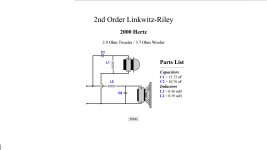
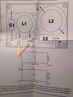
Allen, I finally understand what you're saying. Like in the schematic, R2 has to be placed between + and - terminals after R1. Which would work best?
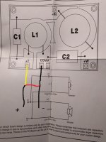
Thanks for your patience. 🙂
They are electrically the same. At speaker frequencies, component layout comes down things like vibration resistance and leads breaking, convenience, heat dissipation.
Last edited:
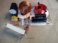
First crossover completed
The crossover components arrived this afternoon and I was able to assemble my very first passive crossover.
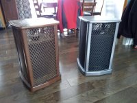
Yesterday I was able to install the new drivers and bring the Sansui SF2 exterior into the 21st century.
One more crossover to go and a bit of mounting work, then I'll be able to hear them for the first time.


Wrapping up
Well, to wrap things up, I got both crossovers done with the attenuation resistors reducing the output of the tweeter by more than 5 db. They sounded awful! The high end was veiled and just seriously lacking.
I removed the resistors for the l-pad portion and it is so much better. Granted, a small reduction in frequencies above 2k would be ideal, I'm using these in my system with a car stereo as the center piece so it's easy enough to use the built in equalizer to reduce the top end a bit.
The SF2's originally had a first order crossover and two 8" mid/bass drivers. Now they have a 2nd order LR with a single up-firing 8" mid/bass driver to integrate with the up firing soft dome tweeter. Both new drivers and the crossovers are a vast improvement over the original configuration. I am very pleased with the outcome.
Thanks for the assist guys and especially Allen.
- Status
- Not open for further replies.
- Home
- Loudspeakers
- Multi-Way
- How do I integrate L-Pad components into crossover?
