If bracket is used than also Vbe multiplier and drivers could all be mounted in the horizontal position together with output transistors. Mihai's pcb is very versatile.
Hi,
My issue is no(or very low) music output.
A test by touching input capacitor gives enough output response.
Regards,
Sunita.
My issue is no(or very low) music output.
A test by touching input capacitor gives enough output response.
Regards,
Sunita.
It's difficult to help you at such distance. There is some mistake, cold solder joint or misplaced component. Who knows?
Sorry Ivan, this seems like you are saying that we should mount the drivers on the same heatsink as the output transistors of the P3a. It may cool the drivers if necessary but the Vbe multiplier Q9 must follow the driver's thermal path independently. So yes, it is OK to fit a separate bracket or strip of thick aluminium to cool and thermally couple just the drivers to the Vbe multiplier or just locate it (Q9) nearby, as in previous P3a versions. However, it is better again and obviously much faster in response, to ensure this by direct coupling as in Rod Elliott's current PCB version which may well have been inspired by earlier threads here or straight from Douglas Self's handbooks. You might recall that Sakis (East Electronics) showed this in the OP of his long P3a comparison thread....... Vbe multiplier and drivers could all be mounted in the horizontal position together with output transistors.
Driver heat dissipation is fairly constant with EF designs but varies widely with CFP drivers. Even so, it is unwise to mount them on the output transistor heatsink with the Vbe multiplier because the greater dissipation of the output transistors will cause the bias to slowly drift and result in thermal runaway at some point.
Agree,look for a better pcb like the original or by Alexmm😉Sorry Ivan, this seems like you are saying that we should mount the drivers on the same heatsink as the output transistors of the P3a. It may cool the drivers if necessary but the Vbe multiplier Q9 must follow the driver's thermal path independently. So yes, it is OK to fit a separate bracket or strip of thick aluminium to cool and thermally couple just the drivers to the Vbe multiplier or just locate it (Q9) nearby, as in previous P3a versions. However, it is better again and obviously much faster in response, to ensure this by direct coupling as in Rod Elliott's current PCB version which may well have been inspired by earlier threads here or straight from Douglas Self's handbooks. You might recall that Sakis (East Electronics) showed this in the OP of his long P3a comparison thread.
Driver heat dissipation is fairly constant with EF designs but varies widely with CFP drivers. Even so, it is unwise to mount them on the output transistor heatsink with the Vbe multiplier because the greater dissipation of the output transistors will cause the bias to slowly drift and result in thermal runaway at some point.
CFP output stage: The Vbe mutiplier must be thermally coupled with the driver transistors, NOT the output transistors.
Output transistors must be on a large heatsink to ensure junctions temperature stay under the max rating.
Driver transistors and Vbe multiplier must be on another small, or very small heatsink. The important point is to ensure a tight thermal coupling. There is no need to keep those cool, as long as the driver junctions temperature stay under the max rating.
Hi All,
Many thanks for your updates.
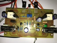
My issue resolved by replacing the input RCA connector. Amplifier tested and work fine fine with +-30V supply.(Tip35/36C). (Strange, produces more heat when using C5200/A1943 as output )
As many of you suggested, "The Vbe mutiplier must be thermally coupled with the driver transistors ,and not with output transistors" . Also thermal coupling for Vbe multiplier with Q6 seems to be sufficient.
Hats off to Rod Elliot for such a simple and perfect design and Manea Mihai, for compact PCB design.
Sunita.
Many thanks for your updates.
My issue resolved by replacing the input RCA connector. Amplifier tested and work fine fine with +-30V supply.(Tip35/36C). (Strange, produces more heat when using C5200/A1943 as output )
As many of you suggested, "The Vbe mutiplier must be thermally coupled with the driver transistors ,and not with output transistors" . Also thermal coupling for Vbe multiplier with Q6 seems to be sufficient.
Hats off to Rod Elliot for such a simple and perfect design and Manea Mihai, for compact PCB design.
Sunita.
Could any colleague give me the Lay Out in pdf of this P3a amplifier? I don't have a lot of .Lay software yet
Last edited:
 ^ TRANSLATION
Could any colleague give me the Lay Out in pdf of this P3a amplifier? I still don't have much software .Lay
Por favor, note que este é um fórum em Inglês
- Home
- Amplifiers
- Solid State
- P3A PCB