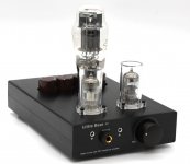
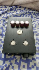
Got myself a Little Bear P7 tube amp a few days ago and paired it with 5670 GE tubes and a GE power tube. I have a few questions regarding how to mod this amp since I have no experience in diy electronics. I have soldered before and I got the hang of it quite fast. The Little bear P7 is the P8 version without a transformer but with a Switching power supply. I have a question on how to increase the gain of the amp to louder volumes to drive even harder headphones. Also at high gain with this amp there's distortion in the low end I'd like to fix. Which capacitors/components do I need to replace/bypass. I wish to use this knowledge to one day create my own headphone tube amp from scratch. I have basic knowledge of circuits boards and the safety procedures to not get electrocuted by capacitors.
Extra question: If I use a tube adapter (5670 to 6SN7) do I need to adjust the voltage from the PCB to run the 6SN7 tubes.
Sorry for all these questions and thanks in advance for helping this noob.
Extra question: If I use a tube adapter (5670 to 6SN7) do I need to adjust the voltage from the PCB to run the 6SN7 tubes.
Sorry for all these questions and thanks in advance for helping this noob.
Attachments
at high gain with this amp there's distortion in the low end I'd like to fix.
I think you will get more response if you also post a schematic. if I "guess" right, the LB P7 has a SRPP like common cathode front end driving a Cathode follower output stage. It also uses direct couple between the input and output stages. This doesn't sound like a gain problem but rather the amp is clipping from the input level without achieving the output level that you want to have. You will have to change the circuit to accept higher level input and/or reduce the output impedance. The problem is this being a direct couple design, you petty much have to recalculate everything.
I think you will get more response if you also post a schematic. if I "guess" right, the LB P7 has a SRPP like common cathode front end driving a Cathode follower output stage. It also uses direct couple between the input and output stages. This doesn't sound like a gain problem but rather the amp is clipping from the input level without achieving the output level that you want to have. You will have to change the circuit to accept higher level input and/or reduce the output impedance. The problem is this being a direct couple design, you petty much have to recalculate everything.
If I post pictures of the pcb will it help ? I can even try to write the voltages and stuff.
Is this Little Bear P7 or P8 schematic?
If so you can try relax negative feedback resistor 10K will give you more gain without affecting others parts, or reduce it to see if distortion is reduced.
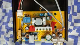
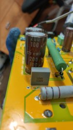
That is the p8 schematic since it doesn't have 4 giant caps on the schematic.the p7 has 4x 450V 100uf caps from nichicon.
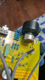
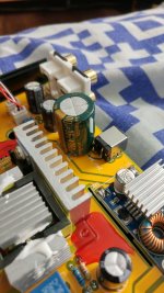
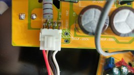
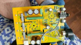
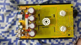
Pictures of important stuff... (I hope)
Took a picture of what I think was important. There's 2 PCB's inside attached by wires. I hope this helps.
Took a picture of what I think was important. There's 2 PCB's inside attached by wires. I hope this helps.
Attachments
-
 20180118_121851_HDR.jpg625.5 KB · Views: 292
 -
 20180118_121818_HDR.jpg661.6 KB · Views: 277
 -
 20180118_121733_HDR.jpg648.9 KB · Views: 317
 -
 20180118_121642_HDR.jpg881.3 KB · Views: 366
 -
 20180118_121617_HDR.jpg506.9 KB · Views: 526
 -
 20180118_121501_HDR.jpg694 KB · Views: 561
 -
 20180118_121301_HDR.jpg821.7 KB · Views: 581
 -
 20180118_120844_HDR.jpg747.7 KB · Views: 562
Yes, you can plug in 6sn7 or other pin compatible tubes in 6080 socket but need to change cathode resistor 2k to 10k for 6sn7 (or about 8mA) Thd about 0.05%, which is same as 6080 for 10k load.
The output impedance for 6080 stage is < 20 ohms (with 10k feedback resistor), it should be able to drive 32 ohm phones but high distortion. However if use as headphones amp, you should reduce cathode resistor of 6080 if the impedance of phones are 32 Ohms to reduce distortion. Be careful not to overload the PSU transformer, or change to large one say at least 50VA if the 6080 is running at 130mA (560 Ohms cathode resistor) or 7W heat dissipation. Even done that, thd is 2% @1V rms out, so you may need to increase feedback to bring down the distortion some more.
The output impedance for 6080 stage is < 20 ohms (with 10k feedback resistor), it should be able to drive 32 ohm phones but high distortion. However if use as headphones amp, you should reduce cathode resistor of 6080 if the impedance of phones are 32 Ohms to reduce distortion. Be careful not to overload the PSU transformer, or change to large one say at least 50VA if the 6080 is running at 130mA (560 Ohms cathode resistor) or 7W heat dissipation. Even done that, thd is 2% @1V rms out, so you may need to increase feedback to bring down the distortion some more.
Last edited:
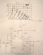
Image attached should be close to what you have. If you plan to make change, make sure you double check and correct errors. I am sure that there will be some. The load line explain what you current problem are. Notice when you lower the output load from 300 ohms to 75 ohms. The negative going output voltage swing is reduce by a lot before the output valve shut off (near 0 mA). The positive going output swing will drive past the 6N5P plate maximum power dissipation (the dotted curve line). The 6N5P turn off is what I think cause your base distortion.
Also notice the 1K resistor between the 5670 and 6N5P. If you make any changes, you will have to make sure the bias of the 6N5P remain valid. Also, I am guessing that B+ is 250V. You might what to measure that.
How low a headphone you what to drive? If you are thinking of a 30 ohms Grado, the best way may be to add a couple of output transformers.
Attachments
Last edited:
Also can i ask if can convert it to stereo preamplifier?
thank you
It should work as a line-amp. I would consider reducing the Negative feedback some using it this way.
Well... I have Monolith m1060's and a Sennheiser HD6xx with a Audio Technica ATH-M50.
Do you have any issues with the Sennheiser? HD600 and HD650 are both 300 ohms headphone. They should work with this amp. The Monolith M1060 are 50 ohms. The Audio Technica ATH-M50 are in the 30s. IMHO, you are better off adding a output transformer for these two.
BTW: If the HD600 has problems, something is not working as it should.
It should work as a line-amp. I would consider reducing the Negative feedback some using it this way.
Do you have any issues with the Sennheiser? HD600 and HD650 are both 300 ohms headphone. They should work with this amp. The Monolith M1060 are 50 ohms. The Audio Technica ATH-M50 are in the 30s. IMHO, you are better off adding a output transformer for these two.
BTW: If the HD600 has problems, something is not working as it should.
The Hd6xx get to an acceptable level in my opinion. Also I got a message from the seller I could use a line powersupply with a minimum of 24V 2A. So this should work right ? GPU572402000WA00: Jameco Reliapro : 24V AC-to-AC Wall Adapter Power Supply : Power Supplies & Wall Adapters I just have to buy a 2.1mm extension. I don't know how I feel about wiring a whole transformer to the AMP though. I might break it.
PS: The M1060 are planar magnetic and the 50ohm doesn't apply really well to to planar magnetic headphones. 50Ohm feels like 250 Ohms in my opinion.
I found an amazing post on how to mod this amp. I'm going to try the 1000uf 35V Panasonic FM mod to see if it does something good.
Little Bear P7 mods based off a P8 thread | Head-Fi.org
Little Bear P7 mods based off a P8 thread | Head-Fi.org
The Hd6xx get to an acceptable level in my opinion. Also I got a message from the seller I could use a line powersupply with a minimum of 24V 2A. So this should work right ? GPU572402000WA00: Jameco Reliapro : 24V AC-to-AC Wall Adapter Power Supply : Power Supplies & Wall Adapters I just have to buy a 2.1mm extension. I don't know how I feel about wiring a whole transformer to the AMP though. I might break it.
PS: The M1060 are planar magnetic and the 50ohm doesn't apply really well to to planar magnetic headphones. 50Ohm feels like 250 Ohms in my opinion.
Edit : Powersupply is not good. Needs to be AC-DC. I was blind sorry.
Well I have fixed the gain issue and it was pretty easy to fix. On the main PCB you have a spot that indicates a 35V 1000uf capacitor but mine came with a 35V 4700uf capacitor, I changed it to a Panasonic FM 35v 1000uf and that increased the gain to where my M1060 sound freaking loud a max gain. The distortion on the low end was semi fixed with a Panasonic FM 25V 1000uf missing on the second PCB where the tube sockets are. It's on the pictures I posted on page 1. Really happy with what I have done. Now I'm waiting on the mail for Vishay/Wima (still haven't decided which ones to go with) 630V 0.1uf FILM capacitors to swap the 3 green and 1 blue 0.1uf 300V ones. That mod is supposed to increase detail in lower frequencies and increase soundstage somehow. I will comeback with an update when the mod is done.😀
No it's not. It sounds good but not as powerful as a a darkvoice. It sounds like crap when you get it. It sounds way batter after modding.
I chose Panasonic caps and wima filter caps.
I chose Panasonic caps and wima filter caps.
Where you able to source the schematics?
Where you able to swap to the 6ns7 tube? if so, did you have to replace the resistor (and which one?)
Reason: I have one that will arrive soon and I got a 6sn7 set (since I thought this was the same as the Darckvoice.)
Where you able to swap to the 6ns7 tube? if so, did you have to replace the resistor (and which one?)
Reason: I have one that will arrive soon and I got a 6sn7 set (since I thought this was the same as the Darckvoice.)
- Home
- Amplifiers
- Tubes / Valves
- Little Bear P7 Tube Amp Simple Questions?