I joined this forum a few months ago hoping that by alchemy some of your knowledge would rub off on me , transforming my education in valves some 55 years ago into something more practical.
For some years now , I have listened to my amplifier without the least worry for its well-being. Until one day it made a strange noise and stopped mid aria.
It had not only blown it's fuse , but a cathode resistor had burnt out , severely damaging the circuit board beneath it. The associated cathode capacitor and grid signal capacitor were also toast along with another nearby cathode capacitor.
Now , I can repair the damage and get it going again without your help , but I doubt whether the results would be satisfactory unless I can understand what happened .
Inspection of the circuit board suggests that this is not the first time this has happened and it occurs to me that it should not have occured in the first place : the fuse should have blown before the fire started.
Should I replace one valve , four valves or all eight valves ?
Should I change all the caps ?
How do I ensure that next time , only the fuse blows ?
The more I read on this forum the more questions seem to occur to me .
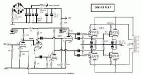
The amp is marked << AL3 by Yves Cochet >> .
It was a kit , not built by me and I have no original circuit for it : but I have back-engineered it and post what I think is the schematic . The OPT's are by Chrétien . Both Cochet and Chrétien have good audiophile reputations in France.
Your expert assistance would be appreciated.
For some years now , I have listened to my amplifier without the least worry for its well-being. Until one day it made a strange noise and stopped mid aria.
It had not only blown it's fuse , but a cathode resistor had burnt out , severely damaging the circuit board beneath it. The associated cathode capacitor and grid signal capacitor were also toast along with another nearby cathode capacitor.
Now , I can repair the damage and get it going again without your help , but I doubt whether the results would be satisfactory unless I can understand what happened .
Inspection of the circuit board suggests that this is not the first time this has happened and it occurs to me that it should not have occured in the first place : the fuse should have blown before the fire started.
Should I replace one valve , four valves or all eight valves ?
Should I change all the caps ?
How do I ensure that next time , only the fuse blows ?
The more I read on this forum the more questions seem to occur to me .
The amp is marked << AL3 by Yves Cochet >> .
It was a kit , not built by me and I have no original circuit for it : but I have back-engineered it and post what I think is the schematic . The OPT's are by Chrétien . Both Cochet and Chrétien have good audiophile reputations in France.
Your expert assistance would be appreciated.
Attachments
Looking at the values of the parts for the first tube, it looks to be designed for an ECC83/12AX7, not an ECC82,12AU7.
The power supply will output 480V before the tubes warm up, exceeding the PS filter cap voltages.
The grid coupling caps should be rated for 630V or more.
The cathode bypass caps should be 330uf 100V and I would add 47R 2W resistors at each EL34 plate for stability. Making the cathode resistors 10W will give you a larger margin for error.
As far as the tubes, the one that was connected where the problems occured should be replaced. The others shouldn't NEED to be changed as they don't share biasing parts, however changing them all might ensure the same thing doesn't happen on a different tube next week.
RE: The fuse. Fuses are there to protect you and your house from fire etc. That fuse blew because eventually there was enough current drawn in a failure mode to blow it.
Use the lowest value you can. I doubt the fuse needs to be higher than 2A but the inrush might require a slo-blo fuse.
Some people fuse the cathodes with 250ma fuses. Maybe someone can chime in on that.
Hope this helps.
Koda
I would recommend to replace 4 tube with a matched quad. The one tube that burned the resistor should be destroyed , the others might be useful in a SEP amp or to play with.
Replace all 4 resistors, but this time mount them elevated from the board using porcelin distances. That way they wont harm the board. Do the same on the other amp as precaution. Do measure the grid voltage when you start the amp again, if any grid departs from zero DC with more then some mV, replace the coupling cap.
You should also change the resistors on the concertina ( 39k / 35k) these should be equal to give a symmetrical signal.
A grid signal capacitor burned out? One feeding an EL34 output tube?
What material was it made of?
What material was it made of?
I would replace the cathode resistor in question and a fresh set of EL34s. They don't need to be matched as they have independent cathode resistors but replace the screen grid feed resistors (330r) with 1k0 3W.
EL34s can be quite damaging when they are old and flash over.
If you use an ECC83/12AX7 instead of ECC82/12AU7 there may be too much gain to stay stable.
EL34s can be quite damaging when they are old and flash over.
If you use an ECC83/12AX7 instead of ECC82/12AU7 there may be too much gain to stay stable.
You might have an intermittent grid leak resistor.
Feedback over four stages is tricky to keep stable, so it might oscillate under certain circumstances.
Feedback over four stages is tricky to keep stable, so it might oscillate under certain circumstances.
Thank you all for your help.
With Koda's comment my first thought was to check that I had not made a mistake over the valve used.
It really was an ECC82 that was there ; and this was consistant with a schematic I had found on the internet for another
Cochet amplifier : The AL2 which is basically the same but with a simple PP ( so you will appreciate that my back-engineering
task was not too onerous , especially as very few of the values were even changed ).
However , having had previous dealings with the sellers of this kit ( they went bankrupt a few years ago ) ,
I investigated further and discovered a study dedicated to this AL2 by someone who had built one , he had even enclosed the original parts list.
And would you believe it : a hand change from ECC82/12AU7 to ECC81/12AT7 .
And the detailed electronic analysis is using the 12AT7 !
One of the most striking changes between the two amps was that the single PP version had a EL34 cathode cap of 220µF rated at 63V.
For the other caps , apparently underrated , the 450V rating was unchanged.
For Traderbam I post a picture of an untoasted grid capacitor – they are all unmarked and I have no idea what they are made of , or value they have.
But the toasted one is still not a short circuit , and it does look as if was a victim rather than a cause.
Would a value of 1µ after the phase splitter be correct ? And 220nF before the EL34 grid ?
My amplifier has never shown anything but good behaviour , I won't say its the best I've ever heard but its transistor predecessor was very unsatisfactory.
So is JonSnell saying I should leave the ECC82 in place ?
For replacing the valve(s) I seem to be receiving conflicting advice !
But I half understand why. Could someone point me towards a good article explaining the 'self adjusting' attributes of the cathode resistance
so that I can have an opinion of my own ?
I have also been led to believe by many articles that matched valves are rarely that. Is this true ?
Am I to assume from your replies that you expect a valve to fail in this way ?
That the best I can do is to protect the other components from the consequences ?
Attachments
Regarding tube matching - yes, if hifi is wanted you need this. And it's not more expensive as most tube vendors does this "for free".
See Music Reference: The Virtues of Power Tube Matching
See Music Reference: The Virtues of Power Tube Matching
With each tube getting it's own cathode resistor, matching isn't nearly as important. It doesn't hurt though.
1u for the phase splitter is way larger than required. The -3db cutoff is only 0.48Hz. 0.1u would work and reduce LF instability.
1u for the phase splitter is way larger than required. The -3db cutoff is only 0.48Hz. 0.1u would work and reduce LF instability.
I am just trying to figure out why the grid coupling cap became "toast". I can see how excess cathode current/voltage would waste a 680 ohm resistor and kill both 100uF electrolytics by over-voltage, but how did the grid capacitor over-heat?It had not only blown it's fuse , but a cathode resistor had burnt out , severely damaging the circuit board beneath it. The associated cathode capacitor and grid signal capacitor were also toast along with another nearby cathode capacitor.
I assume both 100uF were on the same phase? You might need to check the 680 ohm resistor that didn't burn out - it may be damaged. I would measure every resistor value in the vicinity.
Last edited:
I am just trying to figure out why the grid coupling cap became "toast"..
For a start I'm getting confused on definitions, for diagnostics please keep wording simple. 'Toast' is a useless and very poor definition of what actually failed. Could imply 'brown cooked and not just failed'. If the coupling cap really failed to a short circuit forcing g1 hard on by the 68K#B+ from the previous stage, then as the tube failed into internal meltdown perhaps with a short circuited grid and the associated 2K2 grid leak would also be discoloured. Is it so ?
If the coupling cap is discoloured (which I doubt other than the effect of another component being overheated) then the circuit diagram isn't quite right. I wonder what the voltage ratings for these coupling caps are ?
rich
Unaccustomed to being accused of linguistic inexactitude , I delved into my dictionary to find I am indeed guilty of using “casual english” or “idiomatic american” which I totally agree is out of place on an international forum.
“be toast” :
English informal “ be or likely to become finished , defunct , or dead “ ,
American Slang “ to be doomed , ruined or in trouble”,
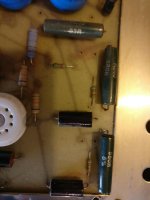
But if you glance at the picture of my ciruit board below you will fully understand why I unthinkingly used this expression , it is a most appropriate description.
If you look carefully you will notice than the resin on the board has vapourized.
Underneath that part of the board are (were) two cathode capacitors . For these I have to admit my usage of 'toast' was figurative only. Both are swollen which I presume means they are no longer functional. And yes they were on the same phase. The other cathode resistor is fine.
As I posted earlier , I have no real knowledge of the value of that coupling cap. But it was probably 220nF / 400v. : what's left of it is not in short ciruit, if that means anything !
The grid leak resistor is the one nearest the remains of the cathode resistor and despite being grilled it still registers 300k ohms.
There are two spots of black deposits on the inside of the glass of the valve which otherwise looks normal.
I hope I have answered all your questions , and thank you for all the help you are giving me.
“be toast” :
English informal “ be or likely to become finished , defunct , or dead “ ,
American Slang “ to be doomed , ruined or in trouble”,
But if you glance at the picture of my ciruit board below you will fully understand why I unthinkingly used this expression , it is a most appropriate description.
If you look carefully you will notice than the resin on the board has vapourized.
Underneath that part of the board are (were) two cathode capacitors . For these I have to admit my usage of 'toast' was figurative only. Both are swollen which I presume means they are no longer functional. And yes they were on the same phase. The other cathode resistor is fine.
As I posted earlier , I have no real knowledge of the value of that coupling cap. But it was probably 220nF / 400v. : what's left of it is not in short ciruit, if that means anything !
The grid leak resistor is the one nearest the remains of the cathode resistor and despite being grilled it still registers 300k ohms.
There are two spots of black deposits on the inside of the glass of the valve which otherwise looks normal.
I hope I have answered all your questions , and thank you for all the help you are giving me.
Attachments
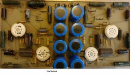
Everyone knows what toasted means. 🙂
That photo is much more useful. I notice the 680 ohm on the left has been incinerated! The tiny resistor next to it is black as night. I wonder whether the grid coupling capacitor looks like this because of its proximity to the incinerated resistor? IOW, has it charred due to receiving heat/flame from the adjacent part rather than having over-heated on its own?
I would be inclined to replace any component that looks charred in any way as a precaution for future reliability. Measure the value of a good grid capacitor and then replace all four. You can measure using a capacitance meter or using a function generator and scope: put cap and a resistor in series and measure the -6dB frequency. I can explain in more detail if required.
Last edited:
Remount the "hot resistors" different; use porcelain distances to have the new resistors away from the board. This also increases the cooling a bit.
Don't forget new tubes ! The one that caused this SHOULD NOT BE USED ! The other can be reused but best result will be with a matched quad where all 4 will work in unison and none will be overloaded.
Don't forget new tubes ! The one that caused this SHOULD NOT BE USED ! The other can be reused but best result will be with a matched quad where all 4 will work in unison and none will be overloaded.
I am about to order two quad sets of matched valves. They were all of the same age ( in hours usage I have no idea , but at least 15 years in age ) , so I presume all ready to fail.
But I still haven't found any good articles on 'self adjusting bias ' to help me understand beyond the simple statement.
With my 3D vision of the circuit board my feeling is that the grid coupling capacitor was a victim of the fire rather than a protagonist.
I've just spent my morning trying to find out about valve failure modes. It is strange but I find all the best discussions are on this forum, Google heuristic algorithms at work ?
I now understand why JonSnell suggested the screen resistors should be changed from 330R to 1K .
Does any one disagree that this , coupled with the fact that the tubes were far from new , is the most likely cause of my conflagation ?
On the naive assuption that the designer chose 330R for a good reason it would seem easier to protect against the consequences of failure rather than risk ruining the amp's audoiphile qualities.
Is an inline fuse on each OPT centre tap acceptable ? If so what value ? 500ma ?
On the capacitor replacement issue , I have found the following quote
<Electrolytics used for cathode bypass must be replaced or bypassed with good quality polyethylene types for the best sound—even though they
can be rather expensive. Very few amp restorations, or even newly designed tube amps for that matter, take this critical step to improve performance. >
I presume the advice in my case is "is bypassed" rather than " replaced" , but is this technically good advice ? I have seen it an amplifier circuit and know it is essential with digital IC's power supplies.
The statement sounds good but will it make the amplifier sound better ?
I also came across this statement
< In Ultralinear Mode the grid stopper action of the resistor is more important than the peak power limiting function - so get that resistor body hard up against the screen pin of the tube socket. > .
Can someone explain to me what this is all about ? If it were not on this forum I would have dismissed it as fantasy.
Self bias works by the fact that the more current flow through a resistor, the bigger the voltage drop (in this case the bias voltage) across it.
If the coupling cap failed and sent voltage to the grid, the tube would conduct wildly increasing the current through the resistor, heating it beyond it's ratings, and destroying it, taking the coupling cap with it due to the higher than normal voltage across it. You can replace the coupling caps with X2 caps for $0.20 each, or you can buy Vishay or Illinois Cap for $2-3 each.
You may or may not hear a difference with bypassing the cathode caps. You can use the same PP X2 safety cap mentioned above for this and save a lot of money, or get "better" parts. You could also use "Audio" capacitors from Nichicon or ELNA.
The purpose of the screen "stopper" is to stop oscillations, and the physically closer to the socket it is, the better it works. As far as changing from 330 to 1k for grid stoppers it won't effect the AF frequency response at all, just RF. Personally I usually use 10K. This resistor and the input capacitance of the grid define a LF filter.
Last edited:
You can find out more info from this well written series. Biasing etc is covered in Volume 2. http://www.sportsbil.com/other/Basic Electronics, Volumes 1-5, (1955).pdf
So you should replace all four in my opinion with new ones that have some writing on them 😉 once you know what value they are. Polypropylene is good.With my 3D vision of the circuit board my feeling is that the grid coupling capacitor was a victim of the fire rather than a protagonist.
A 100uF/100V poly cap is going to be quite rotund. I don't think they will make that much difference...I suggest you buy a dozen, good quality electrolytics, and select the four with closest capacitances. You'll need a means to measure capacitance, of course.On the capacitor replacement issue , I have found the following quote
<Electrolytics used for cathode bypass must be replaced or bypassed with good quality polyethylene types for the best sound—
Still, I'm surprised there isn't a fuse shown. Maybe I missed it. On power amps I always put a fast 630mA in the centre tap of the o/p tranny and I recon if one was fitted, alot of subsequent damage could have been avoided.
- Status
- Not open for further replies.
- Home
- Amplifiers
- Tubes / Valves
- Smoke from a Double PP with EL34s