Total dissipation for 2 plates of a 6SN7 is 5.0 Watts. Max plate Volts is 300V.
Total dissipation for 2 plates of a 6SN7GTA or 6SN7GTB is 7.5 Watts.
Max plate Volts is 450V.
And 6SN7... Filament dissipation is 3.78 Watts.
That size glass envelope fills up with heat real fast.
You will not want to use the zero grid bias spec for the 6SN7. It would require a very low impedance driver, and will almost certainly be too much for the 6SN7 grids, especially if you are using anywhere near the 3.75W dissipation per plate.
I like your idea of using the 6SN7...
Try using the 6SN7... and a 10k Ohm plate to plate hi fi transformer, and an 8 Ohm speaker on the 4 Ohm tap.
You may be surprised, it will not do 1 Watt, but it may be loud enough for you, given the speaker, distance to the speaker, and what you want to hear.
If you like the sound, fine.
Let us know how it works for you.
I am not building guitar amps, but I am building low power hi fi push pull amps with 10k p-p transformers. I have tried Edcore 10k (sounds good), and am working on a Hammond 10k transformer next.
I am finding that using tubes at well less (***) than their max dissipation does work ok.
If you do not like the sound of the 6SN7... amp you try, then you have a good transformer for a push pull amp with 6V6s that you also mentioned, or other tubes.
You do not have to design the 6V6 to be max watts (***), just design for a lower power and sound that you want.
Happy amplifier building!
Is that assuming a triangular current pulse waveform? 0.15 * 300 mA = 45 mA is not equal to 20 mA, but 45 mA/2 = 22.5 mA ~= 20 mA.
Why are the curves so different between the two graphs? They have very different shapes for the same grid voltages.
They are not; just compare a few points that are in both graphs, and you'll see that they more or less match.
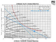
If you want to design an audio amplifier using a 6SN7, I suggest starting with the lower of the 2 graphs on page 4 of the GE data sheet you attached.
Draw a load line on that graph. i.e.:
Start with -8V Ec, 240V Ep, put a dot there (about 8mA).
Use a load of 5k Ohms. 100V/5k Ohms = 20 mA.
240V - 100V = 140V. 8 mA + 20 mA
put a dot at 140V and 28 mA
Now draw a line between the dots at 28 mA and 140V, and 8 mA and 240V, then extend the line all the way to 0 mA. That is a 5k Ohm load line.
Look on the line from Ec = 0V and Ec -16V, versus Ec = -8V. It is not exactly symmetrical.
That will have quite a bit of 2nd harmonic distortion.
But with a 20k Ohm plate to plate load and push pull, that will cancel out quite well.
A 10k plate to plate transformer that has an 8 ohm speaker on the 4 Ohm tap will be 20k Ohms plate to plate.
The impedance of the center tap to either plate connection of a push pull transformer is
1/4th of the plate to plate impedance.
20k plate to plate is 5k plate to center tap (B+).
Do not worry that there will not be enough inductance in the 10k Ohm transformer.
A guitar only goes down to 40Hz, and a good transformer goes down to 20Hz at its rated plate to plate impedance.
Yes, I looked at your other post before I saw this post.
Last edited:
 @flysig - It’s against the Rules to start multiple threads on the same or related topics, as a result, your threads have been merged, and the posts unfortunately are a bit jumbled.
I start by drawing the curve (hyperbola) corresponding to maximum anode dissipation onto the datasheet (red curve in the attached image).The problem is to find a number for the plate-to-plate resistance in a push pull design.
Now you know your operating region needs to be below the red curve.
A common rule of thumb for push-pull class AB is to keep quiescent power dissipation at 70% or less of the maximum power, so if you like, you can draw a second curve corresponding to 70% of anode dissipation.
Now you have to come up with a load line that lies below the red curve, passes through a reasonable operating point, gives you the output power you want (or more), and is practical - meaning you can actually obtain a transformer of that value. I usually try a couple of different lines before I find a good starting point.
With your load line drawn, you can find a reasonable operating point on it. Right around the operating point, your class AB output stage will operate in class A. When current through one valve rises to twice the quiescent current, the other valve will cut off; at this moment, the impedance seen by the anode of the working valve will halve, and the steepness of the load line will double.
So your class AB load line isn't actually straight; in our crude approximation, it has a kink in it, where the resistance halves. If you picked a good quiescent operating point, this kink in the load line will help you use more of the area under the red maximum dissipation curve, i.e., get more power out of your design.
If your datasheet specifies a maximum cathode current, you might want to check that isn't being exceeded, either. Ditto for maximum anode voltage at the other end of the curve; remember, if the datasheet says "300V max", it actually means "600 V max", as the output transformer causes a class A valve output stage anode to swing to twice B+ voltage, and this is allowed for on the datasheet.
Once you have your load line, you can also estimate output power; measure the current and voltage excursions off your plot, multiply them together, and halve the result to get the approximate RMS power. As an example, if you have 20 mA quiescent current and 50 mA peak, that is a 30 mA current swing. Suppose the corresponding voltage swing is from 350V to 50V (300 volts). The product of 0.030A and 300V is 9 watts (peak power); halve that, and your estimate is that this amp will deliver 4.5 watts RMS power to the output transformer primary. Figure the transformer will lose some of that, maybe 20%...which would leave you maybe 3.6 watts to the speaker. (Approximately, of course.)
If everything looks good, it might be time to go build a prototype. If not, draw a new load line, find a new quiescent operating point, and try again.
I usually do this in the (free) image processing software, Gimp. No paper gets wasted, and it's easy to correct mistakes and/or try out several possibilities before deciding on one.
The attached image shows one of my attempts to find a suitable B+ and output transformer primary impedance for a pair of 6BK5 valves. I haven't built this, but I believe it would work, though it might not be optimal (note that anode voltage cannot drop below about 65 volts, which we might be able to improve upon by dropping the quiescent anode current a bit, or using a slightly higher load impedance.)
-Gnobuddy
Attachments
Thanks, that's an interesting way to solve the problem just looking at one tube at a time rather than drawing composite curves.
A question about power limitations. The specific output tube I'm using is the dual triod 6SN7. It lists 7.5W max combined anode power dissipation, with 5W max on either anode. If my quiescent point is below the 3.75W arc (actually it sits at about 70% of 3.75W), then both tubes together at Q are not dissipating more than 7.5W combined. Is this sufficient to say I meet the power limitation even though my load lines rise above the 3.75W line under operation? Your load line stays below the red power limit line on your graph at all times, whereas mine penetrates it about halfway to maximum input voltage swing.
Thanks for that detail!
A question about power limitations. The specific output tube I'm using is the dual triod 6SN7. It lists 7.5W max combined anode power dissipation, with 5W max on either anode. If my quiescent point is below the 3.75W arc (actually it sits at about 70% of 3.75W), then both tubes together at Q are not dissipating more than 7.5W combined. Is this sufficient to say I meet the power limitation even though my load lines rise above the 3.75W line under operation? Your load line stays below the red power limit line on your graph at all times, whereas mine penetrates it about halfway to maximum input voltage swing.
Ditto for maximum anode voltage at the other end of the curve; remember, if the datasheet says "300V max", it actually means "600 V max", as the output transformer causes a class A valve output stage anode to swing to twice B+ voltage, and this is allowed for on the datasheet.
Thanks for that detail!
Gnobuddy got it right.
He used an 8k Ohm load line on the curves.
The half winding (center tap to plate) is 1/4 of the plate to plate impedance. That is because the impedance is proportional to the square of the turns ratio.
(square 1:2 turns = 1/4 impedance).
16k Ohms plate to plate, is 4k Ohms center tap to plate.
For the class A region, both plates are driving 4k Ohms, but they are also aiding each other; so the load that each tube sees in class A is effectively 8k Ohms.
The kink in the load line mentioned by Gnoboddy is where 3rd harmonic distortion rises, even more so for pentode operation. With triodes, the plate resistance gets lower as one tube turns on harder, so the effective parallel plate resistances driving the transformer might not increase by 2 as one tube cuts off, but to a slightly less increased value (depending on the triodes, the operating points, and the load).
Even if the driving resistance increases by 2, the triode rp still has some control over the load.
Without negative feedback, the pentode(s) never did have control over the load.
Ultra Linear falls somewhere between the pentode and triode modes, because UL applies local negative feedback (the ultra linear tap to the screen).
Last edited:
IMO, the composite curve approach is lovely, elegant - and probably quite unnecessary, given the production tolerances of the valves. 🙂Thanks, that's an interesting way to solve the problem just looking at one tube at a time rather than drawing composite curves.
I think so, but am not 100% sure - what happens under conditions of sustained overdrive (this is a guitar amp, after all)?... both tubes together at Q are not dissipating more than 7.5W combined. Is this sufficient to say I meet the power limitation even though my load lines rise above the 3.75W line under operation?
It seems the experienced valve designer answers this by turning out the lights in the room, and looking at the output valves to see if the anodes are glowing dull red. If they're not, you're okay!
I have seen both done, and I don't have the decades of valve experience needed to speak authoritatively to this.Your load line stays below the red power limit line on your graph at all times, whereas mine penetrates it about halfway to maximum input voltage swing.
A practical way to find an answer is once again the "full overdrive in a dark room" test. Anodes not glowing? Your design is fine.
But it's probably a safe guess that the output devices will last longer if not pushed to the limit. Leonidas Fender was an accountant, and could not stop turning up B+ voltage until he was satisfied he was wringing every last milliwatt out of the cheapest output valves he could find. We hobbyists do not have to follow that philosophy...if we want more power, we can simply pick a higher-rated output valve.
You're welcome, that detail confused me at first! 🙂Thanks for that detail!
-Gnobuddy
Thank you. It happens about once a century. 😀Gnobuddy got it right.
I was hoping to be able to use an off-the-shelf 8k Raa transformer with the usual impedance juggling trick - connect an 8 ohm speaker to the 4 ohm tap, or a 16 ohm speaker (pair) to the 8 ohm tap.
The B+ voltage was also chosen for practicality - I was thinking about the possibility of using something like an inexpensive Triad N-68X mains isolation transformer, wired in reverse, so the 240V side becomes the secondary. With solid-state rectification and under light load I guesstimate that should produce around 340 - 350 volts DC.
We were discussing the output impedance of a typical (pentode output) guitar amp on another thread. I came up with a guesstimate as high as a couple of hundred ohms (basically Ra divided by the output transformer's step-down impedance ratio, and halved for class B operation at low power).Without negative feedback, the pentode(s) never did have control over the load.
I didn't have the courage to run my guitar amps unloaded, but diyAudio member Printer2 did. He went off and measured loaded and unloaded output voltage of two of his home-brewed guitar amps.
His numbers translated to 40 ohms output impedance for one amp (push-pull 6V6), and 50 ohms for the other (single ended something).
Contemporary solid-state power amps have output impedances in milliohms. 50 ohms is staggeringly high to those of us who grew up tinkering with transistors. We're not in Kansas any more, Toto! 😱
(My interest in this being not so much bass damping, as the fact that both the bass and the treble frequency response of a guitar speaker driven from a 50 ohm source impedance is very different than the same speaker driven from an essentially zero source impedance.)
-Gnobuddy
A “typical” 12 inch “8 Ohm” loudspeaker driver in either an open cabinet, or a large closed cabinet might have the following characteristics:
6 Ohms DCR (measure with an Ohmmeter).
At DC the impedance will be 6 Ohms, and still be only 6 Ohms at 20Hz.
Above 20Hz, the impedance starts rising as we approach the bass resonance.
At the bass resonance, 50Hz, the impedance may rise to 40 Ohms.
Above 50 Hz the impedance starts dropping to a low again of 6 Ohms, at 300 Hz.
Above 300Hz, the impedance starts rising due to the voice coil inductance, to 25 Ohms at 20kHz.
The voltage of a non-feedback pentode amp with poor damping factor, will pretty much follow the impedance versus frequency of the driver.
But not all is lost:
The low inductive reactance of the transformer secondary winding at low frequencies will increase the damping factor in the bass region.
Exactly! So you get both a bass hump around driver resonance, and a possibly substantial wide-band treble boost, depending on voice coil inductance.The voltage of a non-feedback pentode amp with poor damping factor, will pretty much follow the impedance versus frequency of the driver.
Most guitar speakers for which I've seen specifications seem to have a fundamental resonance around 80 Hz - 110 Hz, rather than 50 Hz.
Low "E" on a guitar is 83 Hz, and there seems to be very little of the fundamental frequency in a guitar signal anyway, so this doesn't seem to be an issue. In fact, many guitar amps have additional high-pass filtering built into the "voicing" as well, trimming away even more bass.
-Gnobuddy
When audio penthodes first appeared on the market, their high impedance was a selling point: the resulting bump nicely compensated for the bass loss due to the acoustic short-circuit caused by the ventilation holes in the back side of the valve radio. If the bump was too much, you could always put a cloth around the back of the loudspeaker as an acoustic damping resistor.
Interesting! I hadn't heard this, but I've wondered if Leonidas was happy with his open-back guitar "cabs" because they acoustically roll off that poorly controlled deep bass hump.the resulting bump nicely compensated for the bass loss due to the acoustic short-circuit caused by the ventilation holes in the back side of the valve radio.
It's quite possible today's guitar speakers are still designed exactly as you described, to work best with high source impedance and an acoustically "leaky" enclosure.
Corollary: if true, then guitar speakers will not sound right when driven by a low-impedance solid-state power amp...appropriate EQ would need to be added.
I'll add that if the driving amplifier source impedance is much higher than the loudspeaker DC resistance, the Q of the speaker around resonance rises to about the value of the Thiele-Small parameter Qms (Q due to mechanical damping only, no effective electromagnetic damping.)
On modern Hi-Fi speakers, Qms is hugely bigger than Qts (meaning an enormous bass peak if driven from high impedance). Modern guitar speakers? I don't know.
I've met a few guitarists I'd like to put a cloth over, in the hope of creating considerable amounts of acoustic damping. 😀If the bump was too much, you could always put a cloth around the back of the loudspeaker as an acoustic damping resistor.
(And I say this as a guitarist myself. 😀)
-Gnobuddy
... "full overdrive in a dark room" test....
Also idle in a dark room.
Most of these schemes will be cathode bias, near class A. Class A gets *cooler* when the near-steady input power is transfered out to a load.
Oh, come on, all necessary data is in the datasheet.
There is an established, old as the Pyramids *graphic* design method which gives you load impedance in 2 minutes, for any conceivable plate voltage you have available.
I do it all the time, if/when I want to design a power stage for a new tube I happen to find ... or to check unrealistic claims by others.
I have posted it somewhere, whether here or in Music Electronics Forum, won´t retype it again from scratch, search for it.
Or read some classic Tube Amplifier design book, that´s the Old Guy way to do it, no computers available way back then.
That´s exactly why all those curves are in the datasheet.
...A guitar only goes down to 40Hz...
82Hz for Guitar. 41Hz for Bass.
It is not certain that all "good" transformers go to 20Hz. Hi-Fi iron for push-pull will beat that. But the selection at 6SN7 impedances is slimmer. However a short bottom octave may not be a flaw in a small guitar amp.
Aside from JMFahey's too-rational points, there are many dozen 12AU7 designs posted to the interwebs. To first approximation, 6SN7 is 12AU7 with 8 pins. 12BH7 is the same a hair bigger. While half these self-proven designs are half-baked, some study will give you food for thought.
I'll offer this. Triodes are not the power-stage that Rock N' Roll was built on. IMHO you want naked Pentodes. There are crates of fine small *power* pentodes at low prices which are easy to match to available transformers.
PRR,
I stand corrected on the pitch.
I guess I would have been out of tune at 40Hz for bass, and 80Hz for lead guitars.
You caught me quite a bit flat.
I have not yet seen a push pull transformer that did not have enough inductance to go down to 20Hz reasonably well. But there certainly must be some that do not, especially depending on how they are applied.
Suppose non-feedback pentodes are used to drive a push pull transformer; and in addition, the loudspeaker is connected to a tap that is less than the loudspeaker impedance (i.e., an 8 Ohm driver on a 4 Ohm tap). What will happen is that the reflected load does not swamp out the primary's inductive reactance at low frequencies. That will roll off the low end early. That might sound OK.
Guitar amps are a different world from Hi Fi amps.
One 'bad' amp that sounded great is the bass amp that blew one of the push pull output tubes during a recording session: Take a listen to Marty Robbins singing "Don't Worry 'Bout Me" in 1959. What a great fuzz guitar sound! To think that a busted amp may have started fuzz popularity.
Aside from JMFahey's too-rational points, there are many dozen 12AU7 designs posted to the interwebs. To first approximation, 6SN7 is 12AU7 with 8 pins. 12BH7 is the same a hair bigger. While half these self-proven designs are half-baked, some study will give you food for thought.
I'll offer this. Triodes are not the power-stage that Rock N' Roll was built on. IMHO you want naked Pentodes. There are crates of fine small *power* pentodes at low prices which are easy to match to available transformers.
The selection of 6SN7 was primarily from finding some rave reviews about that tube in a guitar amp at about 1W. Vpp of 250 in the original design, using a 6K transformer. The guy experimented with a bunch of different transformer impedances and that very low impedance sounded best. Weird but numerous other builders said it was a good sounding amp. 24k looks like a much better plate to plate impedance on the graphs.
Admittedly this design project started for me about a week after surgery, so I was still in a bit of a haze! I have a stack of printed out articles and gobs of bookmarked websites that I have no idea what's in there.
For this iteration I will experiment with keeping the output section clean, creating the distortion in the preamp. Master volume, decent tone stack, good iron, well conditioned power supply. I also want to experiment with a side chain compressor in the preamp, which explains the 6BJ6 remote cutoff pentode for the first stage.
- Status
- Not open for further replies.
- Home
- Live Sound
- Instruments and Amps
- How to determine plate-plate resistance for push-pull?