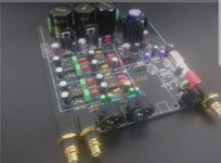
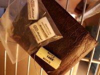
I have some dual Burson opamps to use, a DEXA 5V regulator to replace a 7805, and a discrete clock (but I need to source a 2 pin, 100Mhz oscillator).
Someone recommended replacement for the mono opamps (JRC5534's)...?
Also, for the +-15 VDC, I have a nice PSU to use instead of the onboard rectifier.
Any recommendations for caps and resistors?
I have a schematic I can upload...

Someone recommended replacement for the mono opamps (JRC5534's)...?
Also, for the +-15 VDC, I have a nice PSU to use instead of the onboard rectifier.
Any recommendations for caps and resistors?
I have a schematic I can upload...

Looks like it is set up pretty good, as is, but I suppose I might try and find some Wima fkp2 to replace the 100pf near the op amps. That and I don’t like the scooped-out midrange that the Silmic II offer, I would hunt for some Silmic ARS. That and a 4.7uf 50v from rail to rail on the op amps, of the same flavor.
But that’s just me...
But that’s just me...
Thanks for the suggestions!
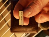
I do have some 0.01uf caps for the Burson's... Can't Remeber the make, but they are French and rated for 1200vdc (dunno why I chose that voltage!)
I'll see if I can source some caps...
I do some some other Wima's from another board, but dunno what model they are.
Here is the schematic...

I do have some 0.01uf caps for the Burson's... Can't Remeber the make, but they are French and rated for 1200vdc (dunno why I chose that voltage!)
I'll see if I can source some caps...
I do some some other Wima's from another board, but dunno what model they are.
Here is the schematic...

That’s great to have the schematic, very nice, not always easy to get from overseas vendors.
I would be weary of any very large capacitors that could add extra inductance, require extensions that negate their performance or over stress any mounting. I usually cut my losses at 250v-400v parts for most everything, and they can be hard to mount at that. I will use blobs of silicone to attach them to adjacent parts to help reduce the point load on traces leads.
Were you going to place them under the board, on the op amp socket pins?
I used those 0.01 caps on my old Xonar sound card next to the opamps...
On this DAC, Ill mount them underneath.
Do you think 4.7uF is overkill? This DAC runs a pair of single and pair of dual opamps...should I cap all 4?
On this DAC, Ill mount them underneath.
Do you think 4.7uF is overkill? This DAC runs a pair of single and pair of dual opamps...should I cap all 4?
If you have room, I would certainly try the 4.7uf electrolytic, I know it’s helped the sound when I have done this. Sounded quieter and smoother with sharper dynamics is the best I can describe it. Definitely worth the small cost of the parts. The general rule of bypassing is 1/10, and while I hadn’t stuck to that before with a few builds, and had just used .01, or .1 and a 47uf electrolytic on each rail. I think there may have been some resonance created between those perhaps or the noise between the rails just needed some attenuation.
I always use a case that allows for an inch or so of clearance on the underside of the board for parts like these. The 1200v parts are going to be of better quality, so if they can fit and aren’t the size of a breakfast sausage, all the better...
I always use a case that allows for an inch or so of clearance on the underside of the board for parts like these. The 1200v parts are going to be of better quality, so if they can fit and aren’t the size of a breakfast sausage, all the better...
You can replace the resistors with 0.1% Vishay non magnetic ones.
The ICs should be soldered directly into the PCB.
The ICs should be soldered directly into the PCB.
Thanks...
Do you recommend just the resistors in the signal path?
They're EXPENSIVE! (at least on Parts Connexion)
Do you recommend just the resistors in the signal path?
They're EXPENSIVE! (at least on Parts Connexion)
Last edited:
It is better to replace them everywhere in the circuit.
Search for Vishay Dale CMF55-143.
In Germany they cost 0.89€/piece.
Search for Vishay Dale CMF55-143.
In Germany they cost 0.89€/piece.
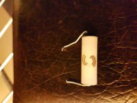
Those look like Solen, I haven't used those but I know the Relcap PPF are very nice parts.
I have been hesitant to solder the discrete op amps int my DACs, there is a decent amount of tension on the pin/socket connection however, and I tell myself it's ok...
I have been hesitant to solder the discrete op amps int my DACs, there is a decent amount of tension on the pin/socket connection however, and I tell myself it's ok...
I held mine (the Bursons) in place using zip ties when I used them on my Xonar.
I have this low jitter clock I want to use...however, the DAC oscilator is 4 pin 100Mhz and the LJC is meant for CD players and uses a 28.xxxxMhz 2 pin crystal.
Discrete Low Jitter Clock GB
I have no idea if its possible to use 100Mhz in it....
I have this low jitter clock I want to use...however, the DAC oscilator is 4 pin 100Mhz and the LJC is meant for CD players and uses a 28.xxxxMhz 2 pin crystal.
Discrete Low Jitter Clock GB
I have no idea if its possible to use 100Mhz in it....
Yeah....doing some reading....
darn!
Also, I posted the wrong schematic...
This is the one...
https://1drv.ms/b/s!AgL_9VHkExp4rgk21pEg8PDTuHcg
darn!
Also, I posted the wrong schematic...
This is the one...
https://1drv.ms/b/s!AgL_9VHkExp4rgk21pEg8PDTuHcg
That looks more like the ones I have seen from similar boards, can’t read it however, the ms site won’t respond to my iPhone, might work on a pc, or may require an account.
It would really help if there was more info from the ess to work from, but I’m sure yours will be more than fine with a small bit of tuning as you have.
One thing that helped my DACs was to add a snubber across the secondaries of the transformers directly onto the diodes. An 18 ohm resistor(not metal film) in series with a .01uf quality film cap, then a single .1uf across the same. You can search for diode snubber and get a better picture, but those values have worked well with the typical 30va transformers that are used on DACs and pre amps. The results are a more clear sound and tighter bass.
Im utilizing this to power the opamps...
Group buy: SSR03 super regulator power supply
So snubbing the IC power rectifier will help as well, or...?
Group buy: SSR03 super regulator power supply
So snubbing the IC power rectifier will help as well, or...?
That link takes me to a picture of a tube amp...
If there is a smaller transformer and a set of diodes, then it should work the same if on another board vs on your board.
If there is a smaller transformer and a set of diodes, then it should work the same if on another board vs on your board.
Tube amp? Weird...
So this DAC requires 2 transformers....
The - +15VDC for the opamps will come from my external PSU...
A 9VAC transformer is used in two inputs for the rest of the board...
It's regulated to 5VDC and 3.3VDC...
Snubbing the rectifier for these two smaller inputs will benefit the sound quality as well?
I haven’t done that separately, have made the change on all at once, both of the 9v, and both of the 12-15v.
Another thought, if you are powering both of the 9v from a single transformer, that may degrade the performance a bit, but should function fine.
Before I started doing this, I used better diodes, but that’s not necessary with this added.
I found a better description of that power supply on Per Anders site, is quite a nice looking arrangement. I would still try the snubber setup, since diodes are inherently noisy, and the cost is pretty low.
Last edited:
- Status
- Not open for further replies.
- Home
- Source & Line
- Digital Line Level
- Help me upgrade my ES9028 DAC


