Reducing cogging
Thank you for the fast answer. I hope it's OK to ask another.
I have read this thread completely as well as the one on the SG4 generator. I believe that I understand the signal generator has the capability to adjust phasing. Is this adjustment to help reduce cogging on an AC synchronous motor? If so, is there a place I can learn about how to measure cogging? Also, doesn't voltage factor into the cogging reduction? If I have missed the answer to these questions in this thread, I apologize.
There is a thread where I measured the cogging vibration of Hurst motors using an Analog Devices accelerometer here: Hurst Motors: 300 RPM vs 600 RPM--Upgrade or Myth?
You can also just put the motor in your hand and adjust the phase for minimum vibration or use a stethoscope.
Reduced voltage will reduce cogging but it also reduces the amount of available torque, and some indicate that it has a negative impact on sound if it gets too low: 'Number9' TT AC motor controller web site finally up | Page 3 | pink fish media
I've built a couple of Nigel's Speed controller in the past using the TDA7293 bridged mode with 80VA trans outputting 230VAC/50hz to power Lenco L75. I observed it tends to get warmish at normal tropic temperature and much cooler at air-conditioned room. I'm set on implementing a TDA7498 module for my own SG4 build in good time.
I've seen the design; a bit of overkill IMHO. It actually uses two TDA7293 100W amps in single ended parallel mode (not BTL) and a dual polarity supply. There is no need to use a 200W amp to drive a 15-20W motor. Likewise it does not need an 80VA output xfmr. That being said, they seem easy to build and should be fairly bullet-proof.
The later Eagle PSU (25W version) uses a TDA7492 (50W total) with a 25VA Amgis toroid output xfmr; it will run a Lenco motor all day and barely break 90°F (32°C).
The later Eagle PSU (25W version) uses a TDA7492 (50W total) with a 25VA Amgis toroid output xfmr; it will run a Lenco motor all day and barely break 90°F (32°C).
Hi Bill,
I appreciate your honest views. Normally I won't go overkill mode, but its often from where I shop for parts, the price difference is hardly any worry between VA models since we're not into mass production for commercial sale where savings is everything and i'm buying one of each. In previous builds, I followed to the letter on their recommendations which was minimum 80VA. I will use your recommendations in the upcoming build.
Thank you again.
Lee
I have built 3 of the Nigel's Speed Controllers. I always felt they might be a bit of overkill. But the build instructions were good and it was the only controller available to semi-literate DIY'ers like myself. Heat dissipation is a problem however.
I have built 3 of the Nigel's Speed Controllers. I always felt they might be a bit of overkill. But the build instructions were good and it was the only controller available to semi-literate DIY'ers like myself. Heat dissipation is a problem however.
Its very essential to buy TDA chips from a legit source where quality is assured. Its scary to experience fakes or lesser grade chips from anywhere and cause havoc later on. I've learned my lessons with one specimen outputting 40V at initial power on (without load). Recently, I had a pair (from legit source) just died from unknown cause. There was absolutely nothing wrong with the circuit, it just died. Replacement was the answer with 1 hour downtime. That's experience for me. I'm waiting for my new Class D module to arrive, wish me luck. 🙂
Lee
AC motor question -probably a dumb one...
I'll say up front that this is probably a dumb question. In an AC synchronous motor (such as VPI or Empire) how do you determine which is the connection for 0 degree and for 90 degree connection to the power supply?
Thank you for your patience.
I'll say up front that this is probably a dumb question. In an AC synchronous motor (such as VPI or Empire) how do you determine which is the connection for 0 degree and for 90 degree connection to the power supply?
Thank you for your patience.
I've seen the design; a bit of overkill IMHO. It actually uses two TDA7293 100W amps in single ended parallel mode (not BTL) and a dual polarity supply. There is no need to use a 200W amp to drive a 15-20W motor. Likewise it does not need an 80VA output xfmr. That being said, they seem easy to build and should be fairly bullet-proof.
The later Eagle PSU (25W version) uses a TDA7492 (50W total) with a 25VA Amgis toroid output xfmr; it will run a Lenco motor all day and barely break 90°F (32°C).
You can never have enough headroom.
I'll say up front that this is probably a dumb question. In an AC synchronous motor (such as VPI or Empire) how do you determine which is the connection for 0 degree and for 90 degree connection to the power supply?
Thank you for your patience.
A good question actually. It determines which way the motor turns (cw or ccw). There are two windings and they share a common connection (AC return). Connect the direct (0°) signal to one winding and the cap (90°) to the other, and the motor will turn in one direction. Reverse the "hot" connections and the motor direction is reversed.
On the Hurst motors, the red wire is the direct connection (0°), black is through the cap (90°) to turn clockwise.
You can never have enough headroom.
In an audio amp, this makes a certain amount of sense, but only up to a point. A motor supply does not have a crest factor as the drive signal is constant. A certain amount of headroom is prudent, usually ~3dB. Anything more than that is a waste of money and adds needless complexity to a design while accomplishing nothing in return.
The NSC could easily have been done with a single TDA7293 and a single ended power supply that would allow the tab of the chip amp to be directly connected to the heat sink (ground) without the need for insulating wafers or hardware. AC coupling the output into the step up transformer would also reduce the chance of failure during frequency switching, the loss of drive signal or unusually high input or output offset voltage.
Last edited:
So I just learned how to solder and made a preamp for my VPI HW19 IV. It was interesting and I'd like to learn to build/assemble more electronics.
The VPI always seemed to run 1.5-2.5 rpm slow with a Hurst 300rpm motor. I suspect that it's because the original owner replaced the platter with a bigger one but didn't change the pulley (does that make sense?). Right now, I have a Music Hall cruise control 2.0 controlling the speed. It works even though the CC is for 3W motors and the VPI motor is 6W. But it introduces some noise into my system and I don't like running gear out of spec.
After doing some research I wanted to get a Phoenix Engineering Falcon PSU, but unfortunately I'm about a year late to that party. But my research on that led me here and I'm trying to understand how this amplifier and the SG4 work and how to build them.
The bottom line is I hardly understand either thread. I guess the SG4 changes the AC frequency from 60Hz to something else and then the amplifier section takes whatever signal the SG4 is putting out and boosts it to the point it can drive the motor? Anyway, normally that wouldn't stop me, but I see that I have to work with AC power and my zero experience and ignorance regarding basic electronics disqualifies me from building this. I also lack the correct tools to do the metal case work.
So what are my options? I can't go on a DIY forum and ask someone to DIFM (Do It Form Me). These aren't for sale somewhere else. Does anyone live near DC and want to work with me on putting one together?
Any advice (direct or point me to search terms/threads I should read) would be appreciated! Merry Christmas!
The bottom line is I hardly understand either thread. I guess the SG4 changes the AC frequency from 60Hz to something else and then the amplifier section takes whatever signal the SG4 is putting out and boosts it to the point it can drive the motor?
The SG4 is a sinewave generator (actually, it generates 4 discrete sinewaves with different phase offsets); you only need one phase if you are going to power an AC synch motor the same way you would power it from the wall (using a phase capacitor on the motor to feed the 2nd winding). You can also use the 0° & 90° outputs to generate both phases for the motor directly which produces lower vibration and greater torque than the phase cap solution. The other 2 phases are for use with 3 phase motors (0°/120°/240°) which does not apply for your motor.
The SG4 is powered by 12VDC and converts that DC voltage into a line-level AC signal that needs to be amplified to the correct level in order to drive a motor. This thread contains a couple of options for doing that, one is based on conventional amplifiers (that get warm with operation), the other uses a class D amplifier which performs the same task but does it much more efficiently and produces little to no heat in operation. The output of the either amplifier is still too low for a 115VAC motor, so the amplified signal is run through a step up transformer to convert it to 115/230VAC. Normally, these transformers are connected to reduce 115/230 line voltage to lower voltage to power a pre-amp etc., but they work in the opposite direction as well, transforming 12VAC into 115VAC.
Anyway, normally that wouldn't stop me, but I see that I have to work with AC power and my zero experience and ignorance regarding basic electronics disqualifies me from building this.
As noted in the OP of the SG4 thread, you should seek help if you are not comfortable working with high power circuits (the amps) or high voltage (step up transformers). Hopefully, someone close by can lend assistance.
Thanks very much. I should have been able to determine this from studying AC motors, but was not able to do so.A good question actually. It determines which way the motor turns (cw or ccw). There are two windings and they share a common connection (AC return). Connect the direct (0°) signal to one winding and the cap (90°) to the other, and the motor will turn in one direction. Reverse the "hot" connections and the motor direction is reversed.
On the Hurst motors, the red wire is the direct connection (0°), black is through the cap (90°) to turn clockwise.
Cheers.
First Time; Long Time
First time poster to this thread after studying it for weeks. Got my SG-4 up & running this evening. DC measurements are dead on and all seems well except middle row on display does not illuminate.
Any remedies/suggestions greatly appreciated.
Also, let me add how educational and interesting this project has been. Thanks to Bill & everyone else for all for the time & effort that went into this. Looking forward to building the complete motor drive for my Empire TT.
Attachments
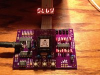
The segment that is missing is labeled "G" on the schematic. Check the connection from pin 6 of U3 -->R16-->display pin 7 on the PCB.
If you used an IDC connector for the ribbon cable, check that the connection at pin 7 of the PCB and the wire to pin 7 of the display are good. You can test those connections while the SG4 is powered up by using an alligator clip and a 330 Ohm resistor. Connect one end of the alligator clip to 5VDC; put the 330 Ohm resistor in the other end and touch the open end of the resistor to pin 7 of the display on the PCB, and separately, on the display itself. That should tell you where the problem is.
If you used an IDC connector for the ribbon cable, check that the connection at pin 7 of the PCB and the wire to pin 7 of the display are good. You can test those connections while the SG4 is powered up by using an alligator clip and a 330 Ohm resistor. Connect one end of the alligator clip to 5VDC; put the 330 Ohm resistor in the other end and touch the open end of the resistor to pin 7 of the display on the PCB, and separately, on the display itself. That should tell you where the problem is.
Still Learning
Thank you for the prompt reply Bill, much appreciated.
I did use an IDG on both ends. I'll go over the schematic and touch up the connections as suggested and report back the results.
(I see now that this should have gone in the SG-4 thread...rookie mistake)
Happy New Year and thanks again for your efforts & understanding...very generous of you.
I'm having time on my hands awaiting delivery of an affordable priced basic TDA7498 amp module from abroad for the SG-4. I've changed my mind for something that could work out better.
Meanwhile I was lurking around and liked what I saw for the price and due implementation.
What I like about this TDA8950 module is not about the power or price but makes my build easier and something that I favor over using a SMPS PSU with a voltage that I can't find or buy here locally. This module require 16VAC to 26VAC instead of the former requiring DC24V or more separately to power up. Just add the required transformers and you're good to go, all in one box. I'm enthused to buy and try this one out. The former is likely to take a back seat for something else in the future.
Example link to the amp module.
2x170W TDA8950 Digital Subwoofer Class D Audio Amplifier Board AMP Module 8950 | eBay
Last edited:
It is one of the few single ended class D amps available so it should work. It uses a bipolar supply so you should be able to connect it directly to a transformer without the need for coupling caps.
Let us know how it works out.....
Let us know how it works out.....
It is one of the few single ended class D amps available so it should work. It uses a bipolar supply so you should be able to connect it directly to a transformer without the need for coupling caps.
Let us know how it works out.....
Right! I will place order for this amplifier and I'm really hoping it works out.
Lee
- Home
- Source & Line
- Analogue Source
- 60 WPC Amplifier for DIY Turntable Motor Drive