Going by some of the other threads I have read giving advice on how to diagnose malfunctioning gear, I figured I’d try doing the same for my issue. I picked up a non-working Ampeg BA115HP (Bass Amp) that from what I can tell has shorted mosfets in the power amp. Foolishly, I replaced only the negative side since I thought the positive side was good. I also replaced the drivers and bridge rectifier(which the previous owner had removed all together). Upon power up, I immediately blew the fuse again. I realize now I should have just gone through it and replaced all the mosfets and transistors but I’m still afraid that may not be all I need to be looking at. I noticed two of the 47 ohm resistors feeding the gates on the power amp mosfets are reading only 27 ohms(should be 47 Ohms) and all four of the .033 ohm 10W resistors are reading around 1.6 ohm. Wouldn’t the resistors just fail all together, not raise or lower their value? All the diodes check good with ohm meter.
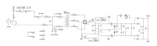
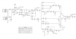
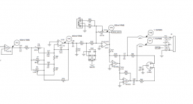
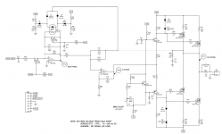
I would like to know the best way to go through this amp and make sure I find all the problem components and save myself from blowing up new ones. I have attached the schematic.
I would like to know the best way to go through this amp and make sure I find all the problem components and save myself from blowing up new ones. I have attached the schematic.
Attachments
I am finding the pics difficult to read.
Don't know about anyone else.
Could you post bigger?
Maybe +50%, or even double the pixel size.
Don't know about anyone else.
Could you post bigger?
Maybe +50%, or even double the pixel size.
Again sorry. I tried to take screenshots so you wouldn't have to download them as PDF to see them.
First, make yourself a "light bulb limiter" and use it. This will prevent blowing fuses and burning up new parts on the bench. A pro might use a variac and ammeter instead, but the bulb is easier for the novice.
Failed 47 ohm resistors do not measure 27 ohms. They generally will measure a lot higher or open. On the other hand, two 47 ohm resistors in parallel would measure about 27 ohms. How would they get in parallel? Through shorted gate to drain output transistors. Check for that.
And all four 0.33 ohm (not 0.033) measuring 1.6 ohms? Unlikely, but your meter leads have resistance. Short your ohm meter probes together and see what you get. Ideally it would be zero ohms, but I am willing to bet you get an ohm or so. You have to ssubtract that from the reading to see what the resistor measures. In practice though, those wirewound 0.33 ohm guys usually are OK or they go open.
The factory schematic file seems pretty clear looking.
Attachments
I have a lightbulb limiter but I only have a 15 watt bulb in it at the moment. When I use it and check secondary voltage on the power transformer, the limiter drops the voltage to half what it is without it.
I also guess you have shorted Mosfets.
Btw, when you are ready, also check the bias trimmer, they are prone to failure. at least turn it a few times.
Btw, when you are ready, also check the bias trimmer, they are prone to failure. at least turn it a few times.
start measuring to find where the excessive current is flowing.I have a lightbulb limiter but I only have a 15 watt bulb in it at the moment. When I use it and check secondary voltage on the power transformer, the limiter drops the voltage to half what it is without it.
You can not measure the parts, if they are soldered in.
Check, if the output transistors are burned by removing the resistors R72, R73, R74, R75.
Check, if the output transistors are burned by removing the resistors R72, R73, R74, R75.
OK, so I just removed the mosfets instead of the resistors and three out of four are bad. They show resistance from gate to drain and they beep on the diode test from drain to source. After removing those, all gate resistors measure correctly at 47 ohms. So now what? How do I confirm that that is all there is wrong with this thing? By the way, what size light bulb should I be using in my limiter?
Yes but should I not be checking to make sure there are not other things that died along with them?
Often you are not able to measure the defective.
When the output transistor are burned, then controlling transistors are also defective.
In your case Q1 and Q4.
When the output transistor are burned, then controlling transistors are also defective.
In your case Q1 and Q4.
Any idea what wattage light bulb I should be running this on? Like I said, the 15W bulb is cutting my voltage in half.
Use a 40W or 60W bulb for that size amplifier.
It will still cut some voltage, but to more reasonable levels, say +/-30V or so, which are fine for testing.
Turn amplifier on, all controls set to 0, no signal injected, no speaker or any load connected, and start by posting here measured +/-rail voltage and speaker out DC voltage.
It will still cut some voltage, but to more reasonable levels, say +/-30V or so, which are fine for testing.
Turn amplifier on, all controls set to 0, no signal injected, no speaker or any load connected, and start by posting here measured +/-rail voltage and speaker out DC voltage.
Ok, well that will have to wait until my parts arrive which probably won't be till this Thursday.
Till then, I'll go get a 60W bulb.
On another note, is it alright for testing purposes to fun the amp through the lightbulb limiter with no heatsinks on the mosfets?
Thanks for all the help so far.
Till then, I'll go get a 60W bulb.
On another note, is it alright for testing purposes to fun the amp through the lightbulb limiter with no heatsinks on the mosfets?
Thanks for all the help so far.
Never run an amp with the heat sinks removed. That is like running a car engine with no coolant.
When running on a bulb, the voltage readings will be fairly useless. The purpose of the bulb is to find out if the amp is drawing excess current - the bulb glows brightly. Voltage readings will not be valid.
When running on a bulb, the voltage readings will be fairly useless. The purpose of the bulb is to find out if the amp is drawing excess current - the bulb glows brightly. Voltage readings will not be valid.
Ok, one more question. The mosfets are mounted to a piece of angle aluminum that then screws to a larger heat sink on the back of the chassis, so it is directly connected to the chassis. When I received this amp, other than the thermal paste, there were no mica insulating pads between the metal back side of the mosfets and the aluminum heatsink it attached to. Should there be? The amp showed obvious signs that the previous owner had replaced the mosfets in the past. Just wondering if they left the insulating pads out when they put it back together?
- Status
- Not open for further replies.
- Home
- Live Sound
- Instruments and Amps
- Bass amp blowing fuses