Question is simple:
Will a transformer rated for 250v 120mA be sufficient for powering a stereo SET 2A3 set amp.
The rating is marginal and I have seen people recommend over rating the mains transformers. I'm not sure if that logic is valid for a class-A SET or is mostly applicable to class-B PP.
The plan is to design for about 50mA thru OPT, thus leaving a few mA on the table for the input circuit/driver.
The markings on the transformer is 250/0/250 volt - I assume this means 500Volt with center-tapped transformer. There are also a 6.3V/2A and a 6.3V/1.5A secondary. If I use the transformer I would load these by about 300mA, alternatively I could use a separate toroid from the scrap box for driver filaments.
My tubes are Golden Dragon Premium. I have not been able to source datasheets for these, but assume that they have a max rating of 300V/60mA
If you are running it as a Full Wave Capacitor Input like the circuit in the bottom left of this pdf then you should be fine.
http://www.hammondmfg.com/pdf/5c007.pdf
http://www.hammondmfg.com/pdf/5c007.pdf
The big question is whether the 120mA is an AC current rating or assumed to be DC current into a specific filter. Transformer manufacturers have gotten a little annoyed with people taking a high voltage winding rated at 400mA AC, rectifying it with a cap input filter, then drawing 400mA from that supply and complaining about problems.
You're probably on the border with this, but reducing the current a little bit in the output stage will help.
You're probably on the border with this, but reducing the current a little bit in the output stage will help.
There is no brand name on the transformer, so finding more details could prove difficult.
Still, looking at the Hammond document linked by MelB above,my options are "Full Wave Capacitor input" or "Full Wave Choke Input".
Am I interpreting correct if I say Introducing a choke will allow me up to 185mA DC?
With output voltage in both cases being 0,45x250=225 volt I guess CRC filtering as well as Cathode bias are both out of the question.
AC and DC mAmp rating should be the same if you run it as a Full Wave Capacitor Input. If you run it with a bridge rectifier you need to de-rate it at 0.62 times the AC mAmp rating. According to Hammond anyhow. But then what do they know about transformers?
LTJ if you use a choke input the voltage you get won't be very high. 500 x 0.45 = 225
Capacitor input gives 500 x 0.7 = 350v
LTJ if you use a choke input the voltage you get won't be very high. 500 x 0.45 = 225
Capacitor input gives 500 x 0.7 = 350v
Member
Joined 2009
Paid Member
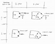
There are four ways you can wire up this transformer to get a voltage of your choosing (see attached drawing). Two of them need a bridge rectifier, which is less convenient if you want to use a tube rectifier but fine with solid state diodes.
For a 2A3 amplifier the standard operating point for the tube is with 250V across it and around 45V across the cathode resistor giving you total of 295V at the plate (and 60mA current per tube). There will be a few volts lost across the output transformer primary impedance so that brings you to a desired B+ of 300V. The closest option is 2-phase (two diodes) with capacitor input filter after the rectifiers. The resulting voltage is a little higher than you want so you'll need to 'waste' about 50V of that. Some further filtering of the supply would be desirable in order to reduce ripple, a choke and cap would be good. With 120mA flowing through a choke with DCR of 200Ohms you'd lose half that 50V you want to drop anyhow.
And instead of using the standard RCA manual operating point for the 2A3. Run it at a slightly higher voltage (which it seems your type of tubes are rated for) and at lower current so as to stay below the maximum power rating for the tube as well as relieve the power transformer a little. For example, 270V across the tube at 50mA (as you suggest) and ~50V across the cathode resistor would then set you up quite nicely.
You'll need a separate floating filament transformer for each 2A3, a 2.5V transformer with centre tap. Edcor and Hammond make suitable filament transformers for 2A3 tubes. And if you avoid using a tube rectifier (usually has quite a lot of heater current draw), this leaves your power transformer without much load on the 6.3V secondary, which you'd use for the input/driver tube. Overall, I think you'd find the transformer you have would work. It will get warm, even hot, depending on how it is designed. I have an amp with a Hammond power transformer that I'm using close to it's rated maximum and it gets quite hot - that's fine, it's designed to operate like that.
NOTE: you can combine capacitor and choke input filters after the rectifier to get other voltages, but I've no experience with that and suspect you'd have to pick capacitors based on experimentation to get the right value for the load current in order to hit the voltage you are after.
Attachments
Last edited:
AC and DC mAmp rating should be the same if you run it as a Full Wave Capacitor Input. <Snip>
First time I've seen that in quite a while, I'd be very cautious and as a former power transformer vendor I had customers who believed this and burned out their power transformers.
Choke input you may get away with drawing close to 100% of the rated secondary AC current, capacitor input regardless of rectifier type (bridge or fullwave CT) I would always stay below 70% of the AC current rating for worst case load conditions.
Hammond might have different guidance for some of their transformers, but I would not apply that without thought to anyone else's.
It strikes me this power transformer is too small, given the effort and time spent building this why not start with a transformer where there is no question of rating inadequacy.
Member
Joined 2009
Paid Member
And, thinking about it some more: The simple calculations I did fall apart if the DCR of the transformer is too high, the result is lots of sag in the resulting rectified voltage when under load. I'd want to measure the DCR of the windings.
First time I've seen that in quite a while, I'd be very cautious and as a former power transformer vendor I had customers who believed this and burned out their power transformers. <snip>
Could be, but then they should not be given that rating. All the Hammonds I've used run at spec with no problem.
They may actually be rated for the DC load current which neatly short circuits the specification issue. (There are several legitimate ways to rate transformers and they are not broadly equivalent)
Member
Joined 2009
Paid Member
Perhaps worth wiring it up (with a fuse), give a resistive dummy load and measure the Vrms you see at the secondary loaded and unloaded, let it run and see if you're happy with how warm it gets.
The Hammond HV CT windings are rated for *DC* current; that's what they are made for.
ALL other transformers you must assume a 1.6 to 1.8 DE-rating. 1 Amp AC is good for about 0.62 to 0.55 Amps steady DC.
That "Hammond" document in reply #2 is flawed. I privately questioned Hammond and it turns out not really BY Hammond. They "got it from the Web". They do NOT do application support(?) and tell users to consult standard references or pay for professional engineering.
Here is my "corrected" version of the document on Hammond's site.
Attachments
Here is my "corrected" version of the document on Hammond's site.
Id trust their onsite document over any private conversation you had with someone who might be mistaken. Hammond usually makes many types transformers for old gear including chokes. Unless they have the words designed for 'capacitive loads with oversized secondary wire gauge' like some toroid XFMR distributor that ships probably 100x the product Hammond does. maybe Hammond has some load testing/regulation diagrams that could clear this up?
Last edited:
I'm using the Hammond 167P18 (18volts @5amps 90VA) for the filaments of my GM70 amps. They each supply 20 volts at 3 amps DC to the GM70s. Using Hammonds sheet for bridge rectifier they say AC amps X 0.62 5amps x 0.62 ~ 3 amps. After 5 hours the measured temperature of these guys is ~ 56C. They are rated at 130C
I'm using the Hammond 300BX for the B+ (800volts @288mAmp) in my GM70 PSE and it is supplying 1060V@170mA to the two GM70's and 500V@25mA to the driver tubes.Using Hammonds sheet for bridge rectifier they say AC amps X 0.62. 288mA x 0.62 = ~180mA After 5 hours they reach ~63C. They are rated at 105C
My experience with Hammonds at least is their ratings and their sheet is correct.
I'm impressed that you can measure the internal temperature of a power transformer. Generally you need to pick a winding that you know a lot about, get a very accurate read of the DCR, then let the transformer run in circuit for 5-6 hours, then remeasure the DCR of the hot winding, then you can make some statements about what the temperature is inside the transformer.
If, of course, you're just measuring the surface temp of the transformer, that doesn't really tell you much.
If, of course, you're just measuring the surface temp of the transformer, that doesn't really tell you much.
Since most people in this hobby are not measuring the internal temperatures and resistances of their transformers the fact that the external temperature of the transformer I'm using after 5 hours is 63C tells me its going to be just fine for decades to come in this application.
I am after all running it right at the manufactures spec'd output why wouldn't it be fine?
I am after all running it right at the manufactures spec'd output why wouldn't it be fine?
How?the fact that the external temperature of the transformer I'm using after 5 hours is 63C tells me its going to be just fine for decades to come in this application.
It's all good and well until you experience failures!I am after all running it right at the manufactures spec'd output why wouldn't it be fine?
The Hammond HV CT windings are rated for *DC* current; that's what they are made for.
ALL other transformers you must assume a 1.6 to 1.8 DE-rating. 1 Amp AC is good for about 0.62 to 0.55 Amps steady DC.
That "Hammond" document in reply #2 is flawed. I privately questioned Hammond and it turns out not really BY Hammond. They "got it from the Web". They do NOT do application support(?) and tell users to consult standard references or pay for professional engineering.
Here is my "corrected" version of the document on Hammond's site.
I like this "corrected" version. Especially for cap input, the B+ will be VERY much dependent on the size of the 1st cap.
If would suggest the original poster to try simulating his proposed circuit before building it. Duncan Amps PSU Designer II is a good enough tool for this.
They will likely find out that this transformer is not up to the task.
....Especially for cap input, the B+ will be VERY much dependent on the size of the 1st cap.....
For "low ripple" at this first cap (how we usually do it in audio), the cap size has only small effect, and only for the small end of what we now usually specify (with today's low electrolytic prices).
OK, if you use oil caps and C-L-C filter you can easily end up "low". This is where simulation may be less tedious than hand calculation.
Attached: 22uFd to 1,000uFd makes 1% difference in average DC. At-Clipping, the ripple-dips make a 4% difference, which is generally no big deal, but generally worth another buck for 50 or 100 uFd.
Attachments
Last edited:
I think Hammond admitted (to PRR?) that they just found that page on the internet and put it up on their own website without checking that it was correct or clear. Now everyone quotes it as a reliable authority.MelB said:According to Hammond anyhow. But then what do they know about transformers?
OOps: just seen PRR confirm that story.
Last edited:
- Status
- Not open for further replies.
- Home
- Amplifiers
- Tubes / Valves
- 120mA traffo sufficient for 2A3?