I'm looking for ideas for making a compact Leach Low-TIM amplifier. Something physically smaller that the original.
The constraint is height of the enclosure, using aluminum Chinese amp enclosures w/heatsinks.
Mid-sized are (2.5") 64mm and 3.3" (84mm) internal height (of the heatsinks) and seem popular.
I was laying out a PC board and kept flipping between L-shaped and pancake configuration for output transistors and couldn't commit.
Almost all possibilities are hell mounting output transistors underneath the PC board. It looked hard to center the insulator and can't see replacing one without gutting the amp.
Possibilities could also be using TO-220 output transistors i.e FJP5200 or down-sizing to a single pair, for a reduced power version.
A SMT design did not offer much (aside from the joy of hand matching SOT-23's); the electrolytic capacitors, emitter resistors, VAS heatsinks eat up any height savings. Probably put the protection circuit on a separate PCB.
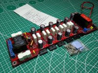
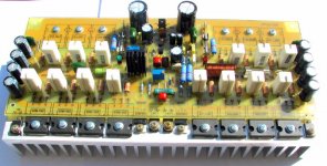
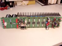
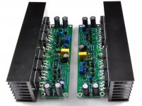
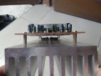
Here are pics of various amplifier PC boards just for looking at overall configuration and ideas.
The constraint is height of the enclosure, using aluminum Chinese amp enclosures w/heatsinks.
Mid-sized are (2.5") 64mm and 3.3" (84mm) internal height (of the heatsinks) and seem popular.
I was laying out a PC board and kept flipping between L-shaped and pancake configuration for output transistors and couldn't commit.
Almost all possibilities are hell mounting output transistors underneath the PC board. It looked hard to center the insulator and can't see replacing one without gutting the amp.
Possibilities could also be using TO-220 output transistors i.e FJP5200 or down-sizing to a single pair, for a reduced power version.
A SMT design did not offer much (aside from the joy of hand matching SOT-23's); the electrolytic capacitors, emitter resistors, VAS heatsinks eat up any height savings. Probably put the protection circuit on a separate PCB.
Here are pics of various amplifier PC boards just for looking at overall configuration and ideas.
Attachments
-
 s-l1000.jpg272.2 KB · Views: 429
 -
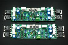 L12-2 amp pcb.jpg106.5 KB · Views: 406
 -
 DX DHR AMPLIFIER 1.jpg160.9 KB · Views: 383
 -
 Jens Leach PCB.jpg52.5 KB · Views: 371
 -
 $_57l L config.JPG200.6 KB · Views: 373
 -
 vhxgt5.jpg43.3 KB · Views: 213
 -
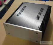 alum enclosure external dimensions W211mm H90mm D257mm_Internal W161mm H84mm D246mm.jpg36.1 KB · Views: 179
Mid-sized are (2.5") 64mm and 3.3" (84mm) internal height (of the heatsinks) and seem popular.
Yes, with near 2U height you can route good OPS for around 80-130 Wt/8 Ohm.
Heatsink dissipation are proportional to square root from height, so it’s probably better to have 2U 400 mm depth case than 3U 300 mm depth.
Try similar layouts:
with TO-247

with TO-220

IPS/VAS could be done as mesonine board, and in case of bigger dissipation it could be heatsinked via bottom (or front) aluminium panel.
Hi
How "down sized" are you going? If you are aiming for the output power within what one pair of MJL21193/4 can do, then you can still have 50-100W. In the same space as two TO-247s, you can use four TO-220s. For the latter, look at the F-pak (fully-encapsulated) types like MJF15030 and compliment. These are 8A 150V.
It is acceptable to use the case as the heat sink if it is thick aluminium. Production amps rated for 60W/ch are built this way, although personally I would prefer to have some actual heat sinking. It depends how hot the idle condition is and how hard you drive the amp whether the dissipation in use is high or low.
There is a distortion advantage to paralleled devices in general, but the specific circuit might work better with single devices.
In either case, the PCB should NOT sandwich the top of the BJT package as that is the hottest part of the device, so it needs airflow. Ideally, you bolt a TO-126-case device to the top of the TO-247 and wire it to the bias network for thermal feedback.
For a small Leach, you can use the cascode input or not. The original Leach did not as it was aimed at modest power. The regulation of the CS voltages is good to retain, though.
As with any PA, it is best to keep the input stage away from the heat of the output stage if you want to keep DC offset from being drifty.
- Status
- Not open for further replies.