At present my power amps take a balanced input and convert to SE via input transformer. I'd like to explore taking the balanced right through the amps as the next phase of evolution, but I've only worked with straight SE OPT before and want to make sure I'm getting my terminology right.
So just looking at the output stage for now, I'd like to use a pair of 45s each in Class A (so each SE, not push-pull) as a differential amplifier, with B+ applied to the centre-tap of the OPT primary so the differential signal drives the secondary and speakers. Each 45 should see a 5k load to B+ and the operating point for each would be normal SE 45 ie 34mA ish, 250V plate. I'll flesh out the design later, but I want to start at the output and get that right.
Is this a simple push-pull transformer ? Sorry if that's the DUMBEST question ever, but what I want to do isn't push-pull, it's balanced single-ended differential so I don't want to make any wrong assumptions when specifying OPT.
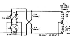
Attached excerpt from an old WE design is the nearest thing I could find, possibly because I'm not searching for the right terms. Any pointers to the right terminology and/or existing designs I can use to understand this better would be greatly appreciated.
So just looking at the output stage for now, I'd like to use a pair of 45s each in Class A (so each SE, not push-pull) as a differential amplifier, with B+ applied to the centre-tap of the OPT primary so the differential signal drives the secondary and speakers. Each 45 should see a 5k load to B+ and the operating point for each would be normal SE 45 ie 34mA ish, 250V plate. I'll flesh out the design later, but I want to start at the output and get that right.
Is this a simple push-pull transformer ? Sorry if that's the DUMBEST question ever, but what I want to do isn't push-pull, it's balanced single-ended differential so I don't want to make any wrong assumptions when specifying OPT.
Attached excerpt from an old WE design is the nearest thing I could find, possibly because I'm not searching for the right terms. Any pointers to the right terminology and/or existing designs I can use to understand this better would be greatly appreciated.
Attachments
Balanced SE is PP by definition... means using an inverter.
PP is two SE using opposite phase signals and combining them to remove everything but the amplified signal by summing up signals.
Allow the comparison, SE = line engine (but a lot less efficient), PP = V engine
PP is two SE using opposite phase signals and combining them to remove everything but the amplified signal by summing up signals.
Allow the comparison, SE = line engine (but a lot less efficient), PP = V engine
Last edited:
I may be getting somewhere in answering my own question. Nevertheless any input confirmation and/or correction will be welcomed.
In this spec, Lundahl say "In class A push-pull, each tube will see a load impedance = 1/2 transformer primary load impedance." http://www.lundahl.se/wp-content/uploads/datasheets/1620_3_7_9202.pdf
So the phrase "Class A push-pull" led me to some useful links, and of course further questions.
The Last Word on Class A
"There are several advantages to push-pull class A amplification. First, the bias current for each side is flowing in opposite directions in the primary of the output transformer, so they effectively cancel each other out. This lack of static, DC offset current in the output transformer means that the core can be made smaller, because it requires no air gap to prevent core saturation from the static DC offset current."
So it looks like what I'm after is a push-pull OPT with a 10K primary (each tube will see 5k), 8ohm secondary. Current rating = 70mA ? (2 x 34mA)
Something like the LL1679 ?
http://www.lundahl.se/wp-content/uploads/datasheets/1679.pdf
Balanced SE is PP by definition... means using an inverter.
PP is two SE using opposite phase signals and combining them to remove everything but the amplified signal by summing up signals.
Allow the comparison, SE = line engine (but a lot less efficient), PP = V engine
Thanks - I think it's the fact that both valves will stay in Class A at all times I'm trying to make sure I'm understanding properly, especially while specifying an OPT. So both valves will conduct at all points of the cycle under maximum signal conditions.
 To avoid confusion, the title of the thread has been changed. Please try to stick with commonly used terms instead of creating your own.
So just looking at the output stage for now, I'd like to use a pair of 45s each in Class A (so each SE, not push-pull) as a differential amplifier
That's not really possible. A differential output stage will have tons of impedance under the cathodes/filaments in the output stage, and isn't likely what you want to go for.
You are correct that in class A, each valve sees half the primary impedance. You aren't going to find much in the way of #45 push-pull schematics, but there are tons of 2A3 push-pull amps that you can adapt to your requirements.
The LL1679 is a bit big for what you're doing. A pair of 45s in push-pull aren't going to get you much more than 6W, so a 45w transformer isn't really called for. The Classic Tone 40-18090 or 40-18037 might be worth investigating, as it's an 8K P-P transformer that should do well with what you're looking to do. There are also oodles of used small vintage push-pull output transformers that are 8K to 10K which have been pulled from 6V6 and EL84 console amps.
Thanks - I think it's the fact that both valves will stay in Class A at all times I'm trying to make sure I'm understanding properly, especially while specifying an OPT. So both valves will conduct at all points of the cycle under maximum signal conditions.
Just keep the bias point closer to the (+) (less (-) ) that your drive signal doesn't push the output tube into cuttoff zone. That is a lower (+) on the cathode if it's cathode biased. Any PP amp can run in Class A if it's biased hot enough. All you are doing is losing some max power you'd get in a Class AB biasing.
Last edited:
How to design valve guitar amplifiers
Lot of reading material for you, well explained, especially the Push-Pull.
You probably saw class A as a marketing claim, looks better than class B, hey it is Class A!.
In reality you try to achieve the better performance for the cost of material and choice of tube/transformers.
Wisdom taught me to enable a smooth transition from class A to class AB. Staying in class A push-pull is possible for big tubes which can dissipate lot of heat. The 45, is one of the weakest tube of audio.
Thanks - appreciate the reading material.
One of my objectives has been to get the output levels down. I previously had a commercially made PX25 which produced 6W and I struggled to get fine control of volume. In SE mode I'm getting about 1W out of each monoblock and it's plenty loud enough, just about perfect.
The tone from the 45 is gorgeous, just beautiful. I may stick with what I have, but I'd like to understand and explore how to keep the balanced differential mode through to the OPT. If I try it, then back away and stick with SE, that's fine because it's a learning experience.
I want to stay in class A because I want to avoid the crossover point into grid-current in each valve, minimise the distortion.
That has a whole hell of a lot more to do with the gain structure of the amp rather than the power produced by the amp.One of my objectives has been to get the output levels down. I previously had a commercially made PX25 which produced 6W and I struggled to get fine control of volume. In SE mode I'm getting about 1W out of each monoblock and it's plenty loud enough, just about perfect.
It's more than easy to make a 1W amplifier with 50db of gain, as well as a 50W amplifier with 1dB of gain. I would strongly recommend taking all the time you need to explore this point before proceeding any further.
I want to stay in class A because I want to avoid the crossover point into grid-current in each valve, minimise the distortion.
You are right on this, however even in class A you have to reverse one phase and feedback is needed to correct the 'sound'.
For your requirements, I would stick to the SET, which you wont find a sound similar in PP amps = for more power requirements, main reason for PP.
Unless your amp sounds too warm, there is no reason to reduce harmonics going to a PP design = less 2nd harmonics, more of the other harmonics.
If you asked earlier in this forum.. for your PX25 amps, you can add 2 resistors in the input of the amp which will further attenuate the Input, giving you a better range on the LOG pot!
I would disagree. Most of the directly heated triode push-pull amps that I've come across use no feedback.You are right on this, however even in class A [...] feedback is needed to correct the 'sound'.
There is a way to "force" class A behavior and "force" AC balance between the two halves of a PP output stage. Configure it as a "long tailed pair" with a CCS tail. I have done this with my PPP KT-120 mono-blocks. A little more extreme than a pair of 45s, but it is a sonically rewarding approach.
You can go into Class B without having grid current. Grid current is nothing to do with crossover distortion. Maybe you are confusing grid current and grid cutoff? They are at opposite ends of the valve response.RhythMick said:I want to stay in class A because I want to avoid the crossover point into grid-current in each valve, minimise the distortion.
....it's balanced single-ended differential....
It's one or the other.
This IS a classic push-pull amp.
It is "differential" at the output transformer (plain push-pull job); also at any input transformer, any common impedance in push-pull cathode circuit(s) (unbypassed cathode resistor?). How "good" it separates differential from common-mode depends on details; but you did not specify any requirement.
You surely want another stage between whatever line-level source and the grids of the '45s. It is not too early to be thinking on that. With the _very_ low amplification factor of the '45, getting full grid swing using the available B+ from the '45 supply may be marginal.
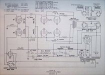
First attachment is a classic WE full-balanced triode amp, and probably runs rich class A. (The 250r field coil is the cathode-bias resistor for the 300b quad.) Second is a general p-p plan, transformer input or balanced source.
If you love the slight curvature of one '45, you may _not_ love the sound of two '45s working differential. The curvatures cancel (nearly).
Transformer to take an available balanced source and drive a single-ended power stage is a very valid design. (Myself, I'd look for an unbalanced output on the source, I'm not that fond of transformers.)
You can go into Class B without having grid current......
Right; and agree that OP may be mixing cutoff with grid current. But a dang lot of tube-maker spec sheets really mix this up. I've seen "Class B" which was really AB1. I've seen others where "Class B" *implied* grid current. IMHO the number should tell us, but it has been used inconsistently.
For reference, the Tung-Sol '45 sheet shows 1W-2W in SE Class A1, but a whopping _18_ Watts in AB2, with a heavy 0.6 Watt drive requirement. You need a third '45 to drive your two power bottles. And that needs ~~50V of drive, so you need a voltage amplifier tube before it, to come up from ~~1V line levels. Because OP's needs are much lower, he does not need a heroic drive; but surely some driver.
Attachments
Last edited:
You can go into Class B without having grid current. Grid current is nothing to do with crossover distortion. Maybe you are confusing grid current and grid cutoff? They are at opposite ends of the valve response.
EVERY time I post a question on this wonderful forum my understanding improves and some misunderstood piece of terminology is clarified, at least a little. Thanks and I'll do more reading around this.
Gabdx - I wouldn't dream to judge anyone elses amp designs or preferences, it's more about being realistic about my next step. Class A SE I've done and am reasonably comfortable with having built both cathode and fixed bias versions. So much more to learn and enjoying the process.
It's one or the other. <snip>
Thank you - lots of great information there.
I have a pair of great sounding monoblocks and I'm in no hurry to change anything. This is a fun learning exercise for me. I'd like to slowly and carefully work through the design and I'm starting from the output transformer backwards. There will be other parts of the design I'll need help with I'm sure.
And you're right - I MAY not like the end result better. The goal for me is to have the skills to be able to design it, build it, then use my own ears to decide which I like best.
There is a way to "force" class A behavior and "force" AC balance between the two halves of a PP output stage. Configure it as a "long tailed pair" with a CCS tail. I have done this with my PPP KT-120 mono-blocks. A little more extreme than a pair of 45s, but it is a sonically rewarding approach.
Thanks John - yes I am expecting to go with LTP and CCS on the tail. At this stage I was trying to get my terminology right for the OPT, but yes that's absolutely where I see this going.
Yes. To make matters worse, every year or so an argument breaks out on here (and presumably other audio forums) about exactly what is the difference between AB and B, and whether AB with a small signal is really A, and whether B necessarily means zero standing current or zero bias etc. Please everyone, I am not trying to kick off this year's version of the argument!PRR said:But a dang lot of tube-maker spec sheets really mix this up. I've seen "Class B" which was really AB1. I've seen others where "Class B" *implied* grid current. IMHO the number should tell us, but it has been used inconsistently.
Whether a CCS tail improves things or not depends on many things. It should ensure stage balance, and so minimise even order distortion at the output. If unbypassed it could boost odd order distortion. It may cause too much bias shift when signal is present due to even order distortion in the valves.
You can go into Class B without having grid current. Grid current is nothing to do with crossover distortion. Maybe you are confusing grid current and grid cutoff? They are at opposite ends of the valve response.
"Crossover distortion" is the term I was looking for, thanks.
Also Garter bias will produce the same result but without the impact on output impedance. The cost comes in a bit more wasted voltage and the need for a decent bypass valve for the garter.There is a way to "force" class A behavior and "force" AC balance between the two halves of a PP output stage. Configure it as a "long tailed pair" with a CCS tail. I have done this with my PPP KT-120 mono-blocks. A little more extreme than a pair of 45s, but it is a sonically rewarding approach.
Shoog
- Status
- Not open for further replies.
- Home
- Amplifiers
- Tubes / Valves
- OPT for Class A Push-Pull?