Hi everybody!
I need some help, I`d like to make some changes to my DAC but I`m afraid I`d screw something up.
Can you please tell me if my thinking is correct?
I have a Cambridge Audio DACMagic that is connected through balanced out on the DAC to unbalanced RCA in on my amp. I chose this because it for whatever reason sounded better then when connected DAC RCA out to amp RCA in.
And now I`m looking to get some higher grade output caps for the DAC and when I opened it, I saw it uses a total of 8 caps - 4x 0,1uF and 4x470uF.
My budget doesn`t allow for 8 quality caps so I was thinking - can I take out these 8 caps and just place one cap on each signal line?
In my limited understanding, it should be the same since its already not balanced 😕
Right? Or am I missing something important.
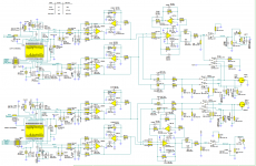
I`ve attached the DAC schematic with marked caps if it helps
Thanks 🙂
I need some help, I`d like to make some changes to my DAC but I`m afraid I`d screw something up.
Can you please tell me if my thinking is correct?
I have a Cambridge Audio DACMagic that is connected through balanced out on the DAC to unbalanced RCA in on my amp. I chose this because it for whatever reason sounded better then when connected DAC RCA out to amp RCA in.
And now I`m looking to get some higher grade output caps for the DAC and when I opened it, I saw it uses a total of 8 caps - 4x 0,1uF and 4x470uF.
My budget doesn`t allow for 8 quality caps so I was thinking - can I take out these 8 caps and just place one cap on each signal line?
In my limited understanding, it should be the same since its already not balanced 😕
Right? Or am I missing something important.
I`ve attached the DAC schematic with marked caps if it helps
Thanks 🙂
Attachments

You should be looking at C299 and C48 for the right channel, and their counterparts for the left channel.
It's an electrolytic and a polypropylene in parallel, you may choose to replace only the electrolytic if you want.
It's an electrolytic and a polypropylene in parallel, you may choose to replace only the electrolytic if you want.
Maybe it would make more sense to get rid of the capacitors alltogether and install a servo to null out dc? What's the point in replacing one 470uF elco for another?
Hi!
Thank you for your replies.
@wwenze - I`m using balanced out, doesn`t the signal pass through C38 for left and C97 for right channel?
@kaputt - a friend of mine replaced his caps with Mundorf and the sound is way better then whatever was inside. I`d like to do the same but not have to change my XLR to RCA cables. Can I just remove all caps that are on the way (as I understand it, those are C1, C2, C38, C39, C40, C41, C42, C97 ) and place two 0,1uF caps for C38 and C97? Would that work?
Can I just remove all caps that are on the way
and place two 0,1uF caps for C38 and C97? Would that work?
Maybe, but it depends on what the input impedance of your amplifier is.
If it's high (100k or more) perhaps 0.1uF will work, or else a larger value of film cap.
The unbalanced output has an extra op amp stage (a balanced to single-ended converter),
and also another DC blocking capacitor, that the balanced output does not need or have.
That's why you may prefer the balanced output.
If you end up doing this, you'll also want to disable the circuitry for the single ended output,
by removing R218, R219, and U61. These parts are in the right channel, similar for left channel.
This will further reduce the loading on the coupling capacitor, so a smaller uF value can be used.
Last edited:
This will further reduce the loading on the coupling capacitor, so a smaller uF value can be used.
A typo, I left out R100 and R101 (right channel) to be removed (or increased in value),
which allows a smaller blocking capacitor value.
Last edited:
Oh ok, I misread the post.
With a balanced-to-RCA connection, usually only one of the balanced signal pins is used, so you can still halve the number of caps to be replaced.
470uF is a lot of capacitance; use a calculator to see how much is enough for you.
The 470uF is in parallel with a 0.1uF because film caps have lower impedance than electrolytic at high frequencies. If you are using a very big film cap, then you only need one capacitor.
R218/R219/U61 are not loading C40/C41
Keep R100 and R101. They provide a path to ground for DC. They also help reduce turn on pop in some situations. You may increase the value if you want, but remember that the effect of increasing their value diminishes once their value become comparable to load resistance.
I`m taking out R218, R219, R194, R195 and disabling U57:A, U57:B, U61:A and U61B.
What value cap do you think would definitely work?
First, we still have to know the input impedance of your amplifier to see if this will work.
It should be 100k or higher. Otherwise, the bass response will be reduced too much.
At the moment the first elements in the amp are two resistors 680ohm and 47K. I took out a cheap 100k pot and placed just two (higher quality) resistors to give me a fixed value and the rest of the volume is contolled digitally.
I hope this answers the input impedance question.
I hope this answers the input impedance question.
At the moment the first elements in the amp are two resistors 680ohm and 47K.
I took out a cheap 100k pot and placed just two (higher quality) resistors
IF a low end roll off at around 20Hz is ok, then you could make this work, especially if
the coupling capacitor is increased to 0.22uF or more. The R100 and R101 should be increased
to about 200k to minimize the bass roll off. If you could replace the 47k that you installed
in the amp with a higher value of 100k or more, that will also help. The same goes for
increasing R72 and R73 to about 200k. Is it a tube or transistor amplifier?
Last edited:
This is a tube preamp / LM1875 chipamp hybrid.
I can change the 47k to 100k, no problem.
What levels of attenuation would that give me?
I can change the 47k to 100k, no problem.
What levels of attenuation would that give me?
This is a tube preamp / LM1875 chipamp hybrid.
I can change the 47k to 100k, What levels of attenuation would that give me?
If you want an input attenuator on the amp, just scale up both input resistors
by the same factor to keep the same attenuation. I'd scale both up by around
a factor of four, from what you have now.
Meaning to keep more or less the attenuation of 680ohm and 47K I`d have to go with 1K3 and 100K.
Got it.
Rayma you`ve been such a help. Thank you so much 🙂
And thanks to wwenze and kaputt for their input
Got it.
Rayma you`ve been such a help. Thank you so much 🙂
And thanks to wwenze and kaputt for their input
Meaning to keep more or less the attenuation of 680ohm and 47K I`d have to go with 1K3 and 100K.
The amplifier input attenuation is only about -0.1dB, so the relative values aren't critical here.
I'd just use 1k and 200k.
Rayma just one thing, tell me please do you know how the change in uF cap size and higher input impendance should affect the sound? Does it matter?
Rayma just one thing, tell me please do you know how the change in uF cap size
and higher input impendance should affect the sound? Does it matter?
You can try that right now, before working on the DAC.
Just increase the 47k to 200k in both channels of the amp.
It will improve the bass response. There should be no downside.
The brand and type of capacitor will affect the sound more than
the uF value from changing say 0.1 to 0.22.
Last edited:
- Status
- Not open for further replies.
- Home
- Source & Line
- Digital Line Level
- Removing / replacing output caps on a DAC