Paid for one set. Thank you so much!
Hi,
Please let us have your postal address.
Else we cannot ship to you.
Many thanks,
Patrick
For those preparing to order parts :
I just realised that Beyschlag MMa0204 1R specified for R19,20 are out of stock at Mouser.
Scheduled delivery August 2018.
As a (equally good) substitute, you may use Beyschlag MCA12060C1008FP500 instead.
Let me know if you come across more parts out of stock.
Patrick
I just realised that Beyschlag MMa0204 1R specified for R19,20 are out of stock at Mouser.
Scheduled delivery August 2018.
As a (equally good) substitute, you may use Beyschlag MCA12060C1008FP500 instead.
Let me know if you come across more parts out of stock.
Patrick
Let me know if you come across more parts out of stock.
The 100n (0805 case) from any manufacturer seem to be scarce at the moment. Newark has some, digikey a very few, mouser on backorder. It may be possible to fit a 1206/1210 part on the pads, don't know.
PCB already done for 0805 pad size.
So 4 solutions for work around :
1)
Use 1206, the solder pads are just 3.2x2mm, so will in theory fit a 1206, at least for C3,4.
Especially if you are willing to scrape a bit of solder resist off for soldering tip access.
But only recommended for skilled persons with lots of SMT experiences.
Might be a bit too fiddly for C31 if you are using servo; see below.
2)
Use Murata X7R 100n 50V for now (GRJ21BR71H104KE01L, 23k stock at Mouser).
They cost ~ 10 cents each, and replace later with film caps when back in stock (15 Jan).
3)
Leave them out for C3,4 (for now), get everything working, and add them later.
Does not affect functional test or stability, etc.
But you need to use (2) for C31 and replace later.
4)
Leave them out completely for C3,4.
Note that for the GB, I included the CCS bias solution.
This makes the circuit much less critical on supply rail voltages.
As such, you do not really need to use the DC servo, even though you might still prefer to.
C31 (plus other components) are only required if you use servo.
Patrick
Last edited:
Please let us have your postal address.
Else we cannot ship to you.
Many thanks,
Patrick
I PMed my postal address a little while ago, but I'll send it again 🙂
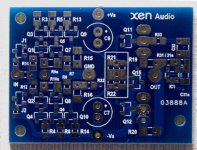
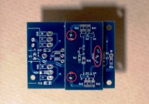
The PCBs arrived.
But this supplier (which we have used for years) recently moved factory and "upgraded" his production equipment.
The result is a small (software?) bug in converting the Gerber files to the solder resist layer.
See who can spot the defect.
This is of course not acceptable to us.
To avoid any risk of the same thing repeating itself, we shall now use another known supplier and remake all boards, at our cost.
Projected shipment date is still last week of November, as promised before.
Shall keep you updated.
Patrick
.
Attachments
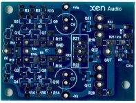
Other than that it provides holes in almost every solder tab for an smd part I can't spot a mistake...

Those holes look like vias. In the wrong spot as mentioned by Stixx
-Chris
Edit:
Nice catch mlloyd1!
-Chris
Edit:
Nice catch mlloyd1!
> Those holes look like vias.
Some are vias, some have special functions, as you will know later.
Not in the wrong spot but deliberately placed.
It is easy to fill those holes with solder while you solder the SMD components. Have use them many times before.
Actually simplifies layout, though not used by others or by industrial software.
> how about this ?
Spot on. Plus some others on the bottom side.
So have to make new even though one can still use all the boards with a bit of resist scrapping.
Patrick
Hi. Can we get the SHPP ver2.0 BOM that will fit the PCB on this GB? I'm ordering the parts for amp PCB, but I cannot proceed until I have the protection pcb as well. Thanks
SB
SB
It is our usual practice that you will be receive all updated documentation once you email to confirm that you received the goods.
These updated versions will not be published in the public domain.
In this case, it includes :
Updated description and BoM of the SL circuit itself including the CCS bias
Description & BoM of the Regulators
Description & BoM of the Cross Feed Circuit
Description & BoM of the SHPP
For the amp itself, using the BoM in the public document will get you 90% of the parts.
You will need in addition (per channel) :
matched pair of 2SC3324BL
matched pair of 2SA1312BL
1x 2SK209GR (Idss ~ 4mA)
4x Susumu 0805 1k
1x Susumu 0805 100R
1x Susumu 0603 100R
The rest you can order afterwards.
Mouser & DK delivery will only take a few days, quicker than you will finish testing the amp.
Sorry for the inconvenience,
Patrick
ALL remaining PCBs arrived and checked OK.
Should be shipping this week, as promised.
You will get email notification of tracking number.
Patrick
Should be shipping this week, as promised.
You will get email notification of tracking number.
Patrick
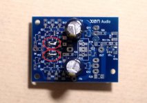
Here info upfront as to how the CCS bias daughter board should be assembled.
There are 5 connections in total :
C6+, C7- extended legs (min 5mm below main board)
Front Gnd wire (0.8mm silver plated copper)
R9a, R10a shorting wire connected to CCS board (0.6mm silver plated copper)
If in doubt please ask first.
Patrick
.
There are 5 connections in total :
C6+, C7- extended legs (min 5mm below main board)
Front Gnd wire (0.8mm silver plated copper)
R9a, R10a shorting wire connected to CCS board (0.6mm silver plated copper)
If in doubt please ask first.
Patrick
.
Attachments
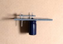
Really neat. You should have put a scale next to the boards to
illustrate the actual dimensions.
😉
illustrate the actual dimensions.
😉
- Status
- Not open for further replies.
- Home
- Group Buys
- Interest for Potential GB for Pioneer Super Linear Circuit