Hi,
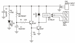
I am looking for some help here. Got a separate +5V supply for pre amp switch input board. I want to delay this for a couple of seconds at power up. Best if its inline like the one attached...but that works for 12V only due to transistor BE break voltage limit. Can somebody suggest a simple solution.
Best Regards
Farooq
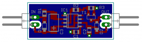
Attachments

you need a 5V relay.
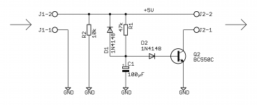
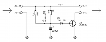
Better to use a Zener or a Red/Green LED instead of that reversed transistor.
Trying to find my camera to post a pic.
Better to use a Zener or a Red/Green LED instead of that reversed transistor.
Trying to find my camera to post a pic.
Last edited:
you need a 5V relay.
Better to use a Zener or a Red/Green LED instead of that reversed transistor.
Trying to find my camera to post a pic.
Actually the relays are already fitted in main board. I wanted to put the delay circuit inline with the Power input jack CON5.
Attachments
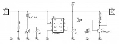
🙂 ,10k only needed if no other load on the 5 volt line.Hi,
+5V supply Best if its inline like the one attached... a simple solution.
Farooq
Mona
Attachments

🙂 ,10k only needed if no other load on the 5 volt line.
Mona
Thanks🙂 ...will try it an post the results.
Sorry no pic, I have mislaid my camera.
The collector of the 2n3904 needs to be moved.
At the moment it is wired like an integrated Darlington. That will drop your 5V down to around 4.1V
The relay should still work.
Instead disconnect the collector of the EF and use a 1k0 resistor to tap into the 5V supply rail. The 2n3904 will operate at a high gain and pass ~4mA to the base of the 2n3053.
The 2n3053 will now operate in saturated mode with an hFE of ~10. That gets the Vce down to ~0.1V or a bit less. Now the relay sees ~4.9V or a bit higher.
The voltages starting at the emitter of 2n3053 are:
3053 0V @ E
3053 0.05V @ C
3053 0.8V @ B
3094 0.8V @ E
3094 0.95V @ C
3094 1.5V @ B
47k/100uF 2.1V @ junction
the 47k passes (5-2.1)/47k = 0.06mA
The 100uF will leak when first fitted. It's voltage may not rise enough to trigger the relay. Reform it slowly before assembly.
The 1k0 passes (5-0.95)/1k = ~4mA. This requires the hFE >>67, >200 would be better, >400 would be excellent.
Last edited:
Sorry Guys for taking your time again.
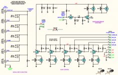
Attached is the circuit of the original 12V one I wanted to modify for 5V.
Also the modified one with Diodes by Mona (I have yet to try it).
May be also need to change the RC values for lower voltage.
Best Regards
Farooq
Attached is the circuit of the original 12V one I wanted to modify for 5V.
Also the modified one with Diodes by Mona (I have yet to try it).
May be also need to change the RC values for lower voltage.
Best Regards
Farooq
Attachments

🙂 ,10k only needed if no other load on the 5 volt line.
Mona
This did not work🙁...I got about 1.5V at output.
Shure, if you make the wrong connection ! 🙁This did not work🙁...I got about 1.5V at output.
Mona
Attachments
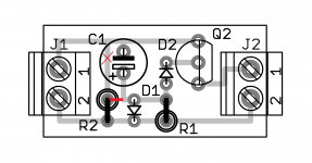
Shure, if you make the wrong connection ! 🙁
Mona
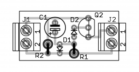
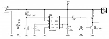
So then this is the correct schematic?
Attachments
No, i made a mistake, looked at the wrong resistorSo then this is the correct schematic?

But with only one transistor there is not enough base current with 47k.
So with the wrong (last = 10k // 47k) circuit in could function, but not much delay left.
Mona
No, i made a mistake, looked at the wrong resistor
But with only one transistor there is not enough base current with 47k.
So with the wrong (last = 10k // 47k) circuit in could function, but not much delay left.
Mona
I came up with another one from net. Using a 2M multiturn Pot to control delay.
Attachments
- Status
- Not open for further replies.
- Home
- Amplifiers
- Power Supplies
- Delay start for relay board