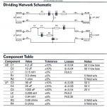
Advice please about replacing the Bennic sand cast resistors in attached schematic.
1. Jantzen sand cast resistors (No 6R just 6.2R)
2. Jantzen Superes (No 6R just 6.2R)
3. Foil resistors based on this article:
Selecting resistors for preamp, amplifier and other high-end audio applications | EE Times
4. Anything else.
Many thanks for any feedback from experience.
1. Jantzen sand cast resistors (No 6R just 6.2R)
2. Jantzen Superes (No 6R just 6.2R)
3. Foil resistors based on this article:
Selecting resistors for preamp, amplifier and other high-end audio applications | EE Times
4. Anything else.
Many thanks for any feedback from experience.
Attachments
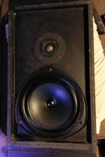
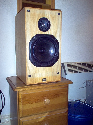
I just checked out the details of your Kef Celeste IV speakers. Attached below.
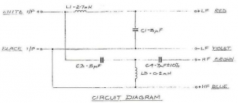
The schematic you attach is actually for the KEF Celeste III.

My good friend Dissi, who designs loudspeaker simulators, at diyaudio dug that one up. 😎
KEF and the BBC built loudspeakers which used a thing called BW3. Or Butterworth. Which is a sort of filter designed for flat power response, rather than strict phase alignment.
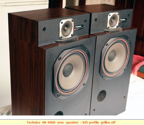
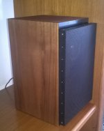
The problem with an 8" bass is the acoustic centre is set about 5cm back. Your own splendid Japanese Technics solved the problem in the SB-4000 by setting the tweeter back a bit:
As it is, the BBC used negative polarity on the tweeter at about 3kHz crossover. That works too.
I have to agree with Jon Snell that changing a sandcast resistor for something else won't make a scrap of difference. It is a near perfect component with negligable inductance. Resistor quality can have effects at radio frequencies, but at audio frequency is irrelevant. Anyway, a well-designed amplifier has an output Zobel (10R plus 0.1uF) that corrects any HF anomalies.
If the 6R is in the bass shunt, it is just a bit of impedance correction. A 6.2R will work exactly the same.
If you want to get up to speed on loudspeakers, can I recommend my favourite thread: Classic monitor designs?
Amongst the rubbish is some great stuff. 😀
The schematic you attach is actually for the KEF Celeste III.
My good friend Dissi, who designs loudspeaker simulators, at diyaudio dug that one up. 😎
KEF and the BBC built loudspeakers which used a thing called BW3. Or Butterworth. Which is a sort of filter designed for flat power response, rather than strict phase alignment.
The problem with an 8" bass is the acoustic centre is set about 5cm back. Your own splendid Japanese Technics solved the problem in the SB-4000 by setting the tweeter back a bit:
As it is, the BBC used negative polarity on the tweeter at about 3kHz crossover. That works too.
I have to agree with Jon Snell that changing a sandcast resistor for something else won't make a scrap of difference. It is a near perfect component with negligable inductance. Resistor quality can have effects at radio frequencies, but at audio frequency is irrelevant. Anyway, a well-designed amplifier has an output Zobel (10R plus 0.1uF) that corrects any HF anomalies.
If the 6R is in the bass shunt, it is just a bit of impedance correction. A 6.2R will work exactly the same.
If you want to get up to speed on loudspeakers, can I recommend my favourite thread: Classic monitor designs?
Amongst the rubbish is some great stuff. 😀
Attachments
if the resistance is within acceptable value there's nothing to gain (although 'round here that can and probably will be debated!)
I can read a crossover like some people can read Egyptian hieroglyphics.
That one was a KEF idea about eliminating bass and distortion frequencies.
A child of its time, IMO. Let's not pretend that the problems of loudspeakers are all solveable.
No rubbish by any means. IMO, the flaw in such designs is the tweeter. I mean, some element of dissatisfaction with the sound must be driving you on here for improvement.
It wouldn't be hard to find a better, more musical tweeter:
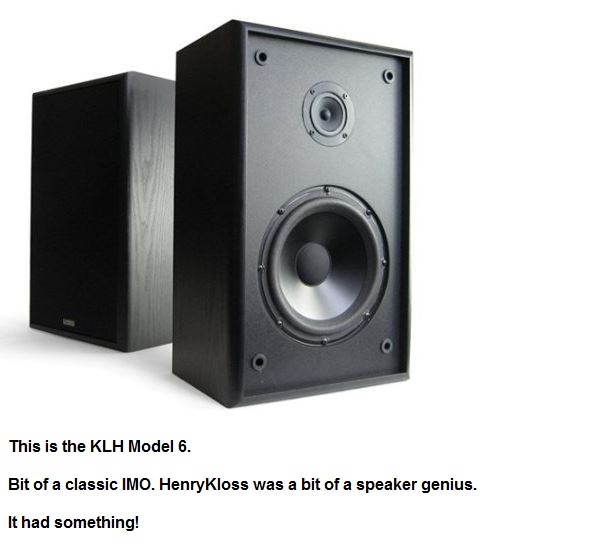
IMO, if a cone works well for bass and midrange, why should it not work well for the top end?
My favourite speaker. I've never heard a dome tweeter that sounded good. TBH, you might have to adjust a resistor in the tweeter crossover here for the right level. But not "Kim Jong-Un" rocket science, IMO.
That one was a KEF idea about eliminating bass and distortion frequencies.
A child of its time, IMO. Let's not pretend that the problems of loudspeakers are all solveable.
No rubbish by any means. IMO, the flaw in such designs is the tweeter. I mean, some element of dissatisfaction with the sound must be driving you on here for improvement.
It wouldn't be hard to find a better, more musical tweeter:
IMO, if a cone works well for bass and midrange, why should it not work well for the top end?
My favourite speaker. I've never heard a dome tweeter that sounded good. TBH, you might have to adjust a resistor in the tweeter crossover here for the right level. But not "Kim Jong-Un" rocket science, IMO.
I agree that a well engineered cone tweeter might be a good solution for all those that find dome tweeters too offensive in any way. I have finished the little project with one and I am amazed over and over again how much a crossover design determines the overall sound quality. Once you get the crossover filter perfected, the rest of the differences are driver based, all else being equal, and those are nowhere near night and day as the price diffrence may suggest. A good middle class driver is all it takes.
edit: Sorry for the OT, I am with all that have concluded there is no point in exchanging a perfectly good component such as sand cast resistor is. Its inductive reactance is not an issue within the frequencies we are interested in.
edit: Sorry for the OT, I am with all that have concluded there is no point in exchanging a perfectly good component such as sand cast resistor is. Its inductive reactance is not an issue within the frequencies we are interested in.
Attachments
Last edited:
If you are upgrading for fun, Mills is my preference.
BUT!! If you are also replacing caps, you should take the ESR (Equivalent Series Resistance) of the caps into account before choosing replacement resistors.
Your total resistance (Cap ESR + R) should remain the same. Replacing older electrolytic caps is especially dangerous as they may have ESRs in the 1-2 Ohm range, while film will be < 0.5.
Take C1/R1 for instance. 4.2uF and 3.3 Ohms. Let's say the original ESR for C1 is 2 ohms.
Total resistance = 3.3 + 2 = 5.3 Ohms.
You replace C1 with a nice film with ESR of 0.4 Ohms.
3.3 + 0.4 = 3.7
Now R1/C1 is 40% off spec! You need to make up for it. We have lost:
2- 0.4 = 1.6
Which we can add to R1:
3.3 + 1.6 = 4.9
For a total R of:
4.9 + 0.4 = 5.3
So you would need to increase R1 to 4.9 (5 Ohms would be within 2%).
5 + 0.4 = 5.4
5.4 / 5.3 = 1.02
Best,
E
Last edited:
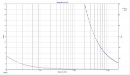
3,3 uF mkp vs. 3,3 uF NPE
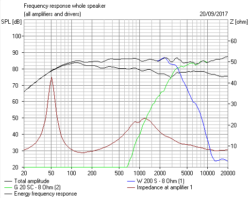
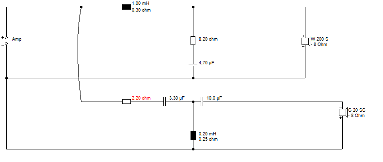
I have done an impedance measurement in CLIO 4,51 and these two aligned in XSim look like this. In the region where it makes sense to use this cap value the difference is negligible. Both caps are about 20 years old. Blue graph is mkp type.
I have done an impedance measurement in CLIO 4,51 and these two aligned in XSim look like this. In the region where it makes sense to use this cap value the difference is negligible. Both caps are about 20 years old. Blue graph is mkp type.
Attachments
Many thanks everyone for your interesting feedback.
I understand that speaker manufacturers use sand cast resistors and electrolytic caps in xovers because: a) they are dirt cheap, and b) they are small, again saving cost on PCBs and electrical tracks. So, I really don't see any downside on replacing them with better parts if they match the electrical and sonic characteristics of the originals.
Troels Gravesen uses the Jantzen Superes in many of his speaker designs.
Erik:
How about I just replace the Kef, Bennic and Alcap bipolar electrolytics with Mundorf ECap AC PLAIN electrolytic capacitors?
All the best.
Hi FTPols,
Film to film should be fine. Modern electrolytic caps are a lot better than old electrolytics. You can change things you don't expect, especially in shunt (going to ground) configurations. In series, well, you could affect the level of the tweeter, and the crossover point.
You can measure ESR relatively cheaply with an impedance jig and Room EQ Wizard.
Impedance Measurement
Best,
E
A problem with modern non-polar electrolytics when used in high current (low impedance) audio circuits such as low frequency crossovers, where the capacitor is used as a bypass for the woofer, is that they are high in capacitance and small in size. Small size and high currents and with an ESR that is moderately high causes internal warming which may lead to failure at high bass levels. If you are going to use a non-polar electro for low frequency attenuation either use one designed for the purpose or make up the value with smaller values in parallel of the smaller sized capacitors. All working voltages should be the same.
Non-polar electro's initially sound okay but they do age over time and the working voltage and capacitance will change. For low frequencies, it will generally go unnoticed, but the crossover frequency will change somewhat over time and this effect may become audible at some later date depending how the speaker is used.
C.M
Last edited:
I suggest only replacing R1 and R2: Get 10 favorite 3R3 2-3W resistors and wire up 3 in parallel to make the 1R.
Many thanks guys for your help.
Regarding calculating the ESR, I have a couple of (insurmountable?) problems.
1. I have no instruments except for a multimeter.
2. Previous owner did a recap and some values are different. E.g. C3 (36uF) is a 33uF +
3.3uF wired in parallel.
HF Circuit: If replacing C1 BP electrolytic with an MKP, I just increase the values of R1 and R2? I don't need to add a small value resistor between C1 and L1?
LF Circuit: Any resistors to be added or values changed if C3 and C4 are changed from BP electrolytics to to MKP?
All the best,
C4 and C3 are the most dangerous to replace, since they shunt to ground. Screwing this up can end up with unexpected dips in impedance, which changes the sound on most amps noticeably. What's weird (and I've seen this happen three times this year alone) is that messing this up affects the treble, not the woofer so much. So people replace these caps and then think they damaged the tweeter or something.
C1 and C2 are relatively safe, but you may end up with a brighter speaker. 🙂 So ideally you would match R1 and R2. If C1 and C2 are already film, then no problem. Replace with other films should be fine.
C4 and C3 though could have ESR of 1-2 ohms each.
C1 and C2 are relatively safe, but you may end up with a brighter speaker. 🙂 So ideally you would match R1 and R2. If C1 and C2 are already film, then no problem. Replace with other films should be fine.
C4 and C3 though could have ESR of 1-2 ohms each.
Last edited:
C4 and C3 are the most dangerous to replace, since they shunt to ground. Screwing this up can end up with unexpected dips in impedance, which changes the sound on most amps noticeably. What's weird (and I've seen this happen three times this year alone) is that messing this up affects the treble, not the woofer so much. So people replace these caps and then think they damaged the tweeter or something.
C1 and C2 are relatively safe, but you may end up with a brighter speaker. 🙂 So ideally you would match R1 and R2. If C1 and C2 are already film, then no problem. Replace with other films should be fine.
C4 and C3 though could have ESR of 1-2 ohms each.
I guess the only way I am going to minimize this ESR problem is to use these BP electrolytics:
Alcap 33.00uF 100V DC High Power Electrolytic Capacitor non-polarised series from Falcon Acoustics, The Leading Supplier of DIY Hifi Components
I advise to calculate/measure exactly the esr values, estimate power input and then simulate in XSim, then you will see clearly what's essentially needed. There is a thread worth reading.
A Test. How much Voltage (power) do your speakers need?
A Test. How much Voltage (power) do your speakers need?
- Status
- Not open for further replies.
- Home
- Loudspeakers
- Multi-Way
- Replacing Sand Cast Resistors in Xover