Bob,
>>I don't mind accusations of being smarter than I am
Don't say that, you are one of the "masters" of this forum. 😎
Regards.
Alain.
>>I don't mind accusations of being smarter than I am
Don't say that, you are one of the "masters" of this forum. 😎
Regards.
Alain.
Alain,
You inspired me so I am in the process of building my version. But one quick question, what are you using as your volume control? I've been having an awful time finding something that seems suitable, and finally ordered a 23 position 4 deck switch from Parts connexion to build a balanced stereo series attenuator. I also made some minor changes to my schematic, but I'll hold off posting until I have something built running well.
One last question. I noticed you aren't using any source degeneration in yours. I had worried that the circuit might be subject to high frequency oscillation without it, but you seem to get excellent results without it. Any thought on that?
Cheers, Terry
Alain,
I have read your posts with interest.
It is time to update my own bosoz.
May I ask is the schematic earlier in the thread the latest version of your CCS?
I note the schamatic you emailed me previously was a little more complex with an additional 20uf electro capacitors and different voltage reference zenor BZX79-10 and 1k resistor to ground.
Also, you appear to be using Black Gate output coupling capacitors in super E configuration. Can you comment on the results.
Ian
metalman,
The volume control was comming with the APOX Kit; similar to the Aleph 1.7
its reed relays with holco resistors to simulate a 255 positions 5K shunt.
I have built 2 prototypes :
1)- with the "chinese" 23 position switch 4 decks 10K ladder the noise is awfull when switching... If some one is interested, I give it for free!!!
2)- Nelson kindly offered me some Electroswsitch, a little better for the noise when switching, but still not my taste...
3)- Had a deal for a APOX kit ; I am working on it at this time ...
I only have a pb, the controller recognizes only 4 of the 8 inputs...
I need a PC to be able to connect to the Apox IR1 board, and the old Win95
pentium I, I have is not working..... I proudly own a working Macintosh, but the program is PC based....
For the "source degeneration", no it works as is, it has passed the SIMetrix simulator, thanks to Henrik for his help setting up the SIMetrix for this design.
Then the 2 protoboards prototypes , and I was quite amaized by the beautifull sound, nothing to be compared to my NAD C350 pre.
More depth, instruments are well separated, beautifull hights, rich female voices, and good bass, also huge image . No oscillation !, and a calculated passband about 0 Hz to 230KHz at -3Db {flat between 0 Hz to >25 KHz}; even with only one Blackgate N 10 microF at the outputs on the prototypes....
The gain is now reduced to 12 Db, I am really confident!!!
I still have a Bosoz board unused, but I will not change of idea, I'll keep it like that....
The only tweak will be to change the bias from 40 mA on each side to 45 mA
to see if "more bias gets better sound...." only have to change the 27 Ohms
and the adjustable -9 volts...
macka,
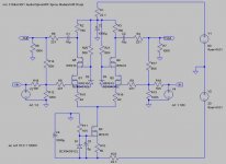
The schematic in Post #14 is the last simplified version from SIMetrix.
But the 20 mF across the Zener diode is missing.... it's needed to smouth the voltage of the zener.
Plus there are 2 * 1/2 watt 5.1 Ohms with 2* 1000 micro F plus 2 * Cerafine 47 micro F on the power supply +60 Volt and -9 Volt
because I have an external power supply with 6 feet cables....
See you soon when finished...
Regards.
Alain.
The volume control was comming with the APOX Kit; similar to the Aleph 1.7
its reed relays with holco resistors to simulate a 255 positions 5K shunt.
I have built 2 prototypes :
1)- with the "chinese" 23 position switch 4 decks 10K ladder the noise is awfull when switching... If some one is interested, I give it for free!!!
2)- Nelson kindly offered me some Electroswsitch, a little better for the noise when switching, but still not my taste...
3)- Had a deal for a APOX kit ; I am working on it at this time ...
I only have a pb, the controller recognizes only 4 of the 8 inputs...
I need a PC to be able to connect to the Apox IR1 board, and the old Win95
pentium I, I have is not working..... I proudly own a working Macintosh, but the program is PC based....
For the "source degeneration", no it works as is, it has passed the SIMetrix simulator, thanks to Henrik for his help setting up the SIMetrix for this design.
Then the 2 protoboards prototypes , and I was quite amaized by the beautifull sound, nothing to be compared to my NAD C350 pre.
More depth, instruments are well separated, beautifull hights, rich female voices, and good bass, also huge image . No oscillation !, and a calculated passband about 0 Hz to 230KHz at -3Db {flat between 0 Hz to >25 KHz}; even with only one Blackgate N 10 microF at the outputs on the prototypes....
The gain is now reduced to 12 Db, I am really confident!!!
I still have a Bosoz board unused, but I will not change of idea, I'll keep it like that....
The only tweak will be to change the bias from 40 mA on each side to 45 mA
to see if "more bias gets better sound...." only have to change the 27 Ohms
and the adjustable -9 volts...
macka,
The schematic in Post #14 is the last simplified version from SIMetrix.
But the 20 mF across the Zener diode is missing.... it's needed to smouth the voltage of the zener.
Plus there are 2 * 1/2 watt 5.1 Ohms with 2* 1000 micro F plus 2 * Cerafine 47 micro F on the power supply +60 Volt and -9 Volt
because I have an external power supply with 6 feet cables....
See you soon when finished...
Regards.
Alain.
Hi to all, just some news.
My CCS-X-Bosoz is finaly working !!!!!
It took me some time to have the 2 channels working at the same level,
but with 2 * 6.8 volts paired zeners ; it's working fine.
Absolutly no clicks or noise while changing the volume, a must!
The only point is I have too much gain on the HDCD input, about 3 Db
but for the rest, all is fine.
Works without any problem with the remote, and the A75 El Diablo
is working balanced now!!!
Even the 12" self powered Subwoofer works well on the RCA output's
Great sound !🙂
I'll post some pictures next week...
I am a very happy DIYer.....
Now time for the enclosure of the ONO......
Regards.
Nelson, thanks for the Bosoz design.
Hope to be able to convert it into a X2 soon.
Alain.
Great news Alain, I look forward to seeing pictures.
About the zeners you mention, are you talking about input protection for the MOSFETs or are you using them for something different? I'm not sure how using zeners would correct channel imbalance, so you have me a little confused. I'm about 2/3rds finished building my version now, so if there is an adjustment needed that you have found I am very interested to know more.
Congratuations!!!
Alain,
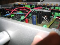
What did you use to connect the power supply to the pre?
Could you describe the connectors and the wiring you used?
Very nice looking Pre... good stuff (as usual!) 🙂
What did you use to connect the power supply to the pre?
Could you describe the connectors and the wiring you used?
Very nice looking Pre... good stuff (as usual!) 🙂
moe29,
I used connector from germany I think: Amphenol C16-1
Digikey references:
361-1040 / 361-1041 / 361-1035 / 361-1038
They are 250 volts 8 amps 7 positions connectors with locking ring.
and I have used #16 copper wire with shielding plus expandable sleeve
long: 2 meter.
I needed 7 position for :
1) +60 volts
2) Reference 0 Volt common for +60 and -8 volts
3) -8 volts
4) +5 volts for the 4 entry boards
5) 0 Volt
6) +5Volts for main controller and stepped attenuator
7) 0 Volt
One set is for the CCS-X-Bosoz
the other for the ONO {here only 6 positions used} 2 times +-50 Volts DC
metalman,
No the 2 zeners are for each CCS's, and must be equal to give the same current in each channel... current is about 80 mA... 40 mA for each IRF610
I have found 2 at 6.73 volts and it works great ; only a few mV of difference
at the output with 300mV sine wave at the input
For the input's protection I have used the common 9.1 volts 500mW
1N5239 in opposition...
And good luck for all you DIY creations. .😉
Regards.
Alain.javascript:smilie(' ')
')
I used connector from germany I think: Amphenol C16-1
Digikey references:
361-1040 / 361-1041 / 361-1035 / 361-1038
They are 250 volts 8 amps 7 positions connectors with locking ring.
and I have used #16 copper wire with shielding plus expandable sleeve
long: 2 meter.
I needed 7 position for :
1) +60 volts
2) Reference 0 Volt common for +60 and -8 volts
3) -8 volts
4) +5 volts for the 4 entry boards
5) 0 Volt
6) +5Volts for main controller and stepped attenuator
7) 0 Volt
One set is for the CCS-X-Bosoz
the other for the ONO {here only 6 positions used} 2 times +-50 Volts DC
metalman,
No the 2 zeners are for each CCS's, and must be equal to give the same current in each channel... current is about 80 mA... 40 mA for each IRF610
I have found 2 at 6.73 volts and it works great ; only a few mV of difference
at the output with 300mV sine wave at the input
For the input's protection I have used the common 9.1 volts 500mW
1N5239 in opposition...
And good luck for all you DIY creations. .😉
Regards.
Alain.javascript:smilie('
')Ahhhh ... I understand now. I elected to put a 50ohm trimpot in my CCS so I can dial in the bias (and maybe play around with the effect of different bias levels). I am getting quite excited as I have finished assembling the circuits now and the trafo's and chassis materials should arrive this week. Can't wait to have something ready that is worth starting a new thread.
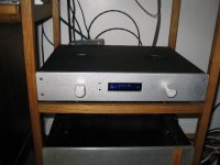
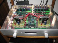
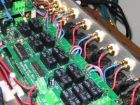
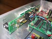
The front pannel with display and encoders...
I had a hard job to encase all 6 mm deeper in the back of the front plate.
It was the last one's .
I expect to close it for long time...
The temperature is low even after 1 full day burnin...
I start now with the enclosure of the ONO.
Regards.
PS:
The sound... well, after a week of listening, nothing to add about...
beautifull definition, the CD's have now gained definition, space
and huge dynamics. It's a great pleasure to have such a baby
and if some one want to build one ; go ahead you won't be disapointed.
Alain.
Attachments
Asen,
>> here can I read opinions on CCS-X-Bosoz Vs. Aleph P 1.7? Thanks
Well, I have no clues about Aleph 1.7 but the 2 designs are similar
The Aleph 1.7 has 2 CCS's on each side of the IRF610's
and is not Xed, but has adjustable gain
The CCS-X-Bosoz is a somewat simpler design, but has a common CCS
for the 2 IRF610's and is Xed...
In my setup the output attenuator is the same as the Aleph 1.7 a 5K Ohms
with 255 steps built with reed relays.
I am currently making attenuators for each input ; to be able to maximize
quality.
Both design are pure Class A and work with high bias.
My preference goes to the X-Bosoz, because of the X giving great advantages
upon the simpler Bosoz.
Regards.
Search about Aleph 1.7 in Stereoplile
What they and I hear is an aspect of sound quality that transcends the general experience of reproduced audio; a quality that cannot be specifically addressed by system matching, cables, or speaker substitutions. In the context of the ART, and to a significant degree one or two related solid-state preamplifiers that use a single FET as an amplifying stage (the XTC PRE in the UK and the Pass Aleph P in the US), this quality can be considered as an absence of previously unidentified, almost unsuspected degradation present in much established amplification. I invite you to keep a sense of proportion when I claim that, compared with worthy zero-feedback designs, conventional amplifiers impose a significant "graying" of dynamic expression, a falsification of timbre, a shift of truly natural tonality, and a smearing of temporal definition. There may also be an associated loss of rhythm, a blurring of the delicate nuances of the leading edges of natural sounds.
fullswing.com/passlabs
Since the input signal travels through only one gain device, it exhibits a purity bettered only by no gain at all.
And so on...
Alain.
nice
Nice! I thought I did a lot of work on my BOSOZ, but I could never make one of those! How long did it take?
Nice! I thought I did a lot of work on my BOSOZ, but I could never make one of those! How long did it take?
lgreen,
>> How long did it take?
Well about 250 hours ; including drawings, 2 set of prototypes
with 2 different attenuators... not too much.
Regards.
PS: The first model takes about twice the time than the next one's!!!
Alain.
>> How long did it take?
Well about 250 hours ; including drawings, 2 set of prototypes
with 2 different attenuators... not too much.
Regards.
PS: The first model takes about twice the time than the next one's!!!
Alain.
...<edit>In the context of the ART, and to a significant degree one or two related solid-state preamplifiers that use a single FET as an amplifying stage (the XTC PRE in the UK and the Pass Aleph P in the US), this quality can be considered as an absence of previously unidentified, almost unsuspected degradation present in much established amplification. ....<edit>
Sorry to revive an old thread...
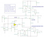
The XTC (the one that I owned anyway - and at least one other I have seen) although claiming to be a single ended class A FET - actually isn't.
The only FET device in it, is the OPAMP servo.
Here is a schematic I drew of mine. (please note - the software I use did not have models for the transistor types used, so I did a few substitutions, with notes.)
There are some more internal pics of the pre-amp here.
Attachments
- Status
- Not open for further replies.
- Home
- Amplifiers
- Pass Labs
- CCS-X-Bosoz Pictures