Morgan Jones's Statistical Regulator is a CCS feeding a shunt regulator (though all SS parts in his design). He shows pretty impressive performance figures in the book and implements it (I believe) in a phono design.
I'm coincidentally in the middle of power supply with SS CCS and tube shunt regulator right now. It will feed Class A line level. I could get the same ripple rejection with chokes and caps, but wanted to try something different. It will also let me adjust my B+ a little more easily (than swapping input caps and rectifier tubes).
I'm coincidentally in the middle of power supply with SS CCS and tube shunt regulator right now. It will feed Class A line level. I could get the same ripple rejection with chokes and caps, but wanted to try something different. It will also let me adjust my B+ a little more easily (than swapping input caps and rectifier tubes).
The noise performance is actually pretty good, when you look at the ratio of the noise voltage and the DC voltage. There is not much 1/f noise and the spectral density of the white noise voltage (expressed as RMS value in 1 Hz) is about sqrt(2 q V^2/I), with q the elementary charge (1.6022E-19 C), V the DC voltage across the tube and I the DC current through it.
One thing to look out for is the ignition delay. Depending on the amount of radioactive material in the tube and the amount of light shining on it, the delay can vary a lot. I once measured 85A2 tubes of four different brands in darkness and found values from dozens of microseconds to seconds.
One thing to look out for is the ignition delay. Depending on the amount of radioactive material in the tube and the amount of light shining on it, the delay can vary a lot. I once measured 85A2 tubes of four different brands in darkness and found values from dozens of microseconds to seconds.
As far as I know they always do ignite eventually, once cosmic radiation has ionized a gas atom that accelerates enough to cause an avalanche effect, but that can take many seconds.
I've used VR tubes with good results, and in this case simply replacing an 0D3 with a 5W 150V zener results in a failed zener and they almost always fail shorted.
As others have said regulation isn't usually required for class A pre/line/drivers and in reality you can use a regulated SMPS from eBay for under $7CAD that has less noise and can take a larger filter cap. It's also adjustable from 45V - 390V (I'm using one for the front end of a class A tetrode amp set at 390V, the main supply only outputs 310V)
Regulation becomes beneficial (or a low impedance supply) when using fixed bias in amps biased towards class B because of the large difference between idle and peak current.
Some people also find regulation improves sound on a phono stage but I have found it not necessary in my builds.
Regarding the thread starter's question about recommended reading, I found the books and articles listed below very interesting. Mind you, they are all meant for engineers and physicists and they deal mainly with the properties rather than the applications of cold cathode tubes. If you're looking for an entry-level description of what voltage regulator tubes are good for, these references are useless.
G. F. Weston, Cold cathode glow discharge tubes, London ILIFFE Books, Ltd., 1968
Philips data handbook ET7 (electron tubes part 7), Gas-filled tubes, August 1975
A. van der Ziel and E. R. Chenette, "Noise and impedance measurements in voltage regulator tubes", Physica, vol. XXIII, 1957, pages 943...952
J. F. Dix and K. B. Reed, "Cold cathode discharge tubes - Impedance and noise properties", Electronic Technology, vol. 39, no. 1, January 1962, pages 31...37
As far as I know they always do ignite eventually, once cosmic radiation has ionized a gas atom that accelerates enough to cause an avalanche effect, but that can take many seconds.
That means several seconds of high, unregulated, voltage.
Yes, that's exactly what it means.
With my 85A2 voltage reference tubes, I found that the Haltron had this behaviour, the NEC always started up in a few dozen microseconds and the Philips needed a few milliseconds. The Pope at first needed milliseconds, but its delay slowly decreased during the measurement.
With my 85A2 voltage reference tubes, I found that the Haltron had this behaviour, the NEC always started up in a few dozen microseconds and the Philips needed a few milliseconds. The Pope at first needed milliseconds, but its delay slowly decreased during the measurement.
The 85A2 is a precision reference tube, when operated near 3mA
conventional use was to feed them from some rectified voltage and filter the RC filtered output into a Long tailed pair used as an error amplifier in the same power supply.
See the following snippet from tektronix "Circuit concepts-Power supply circuits april 1969" a worthwile read because it explains tube series regulators very well.
Back in the day when germanium transistors appeared, there was little in the way of an stable voltage reference, I have a early Philips PE4801 germanium based power supply 0-30V, it uses a 85A2 as a reference. OC76 differential amplifier.
Attachments
With VR tubes you get also visual status indication. When zeners are visual, they often give magic smoke as well .. 😀
Why would an 0A2 initially strike then 2 seconds later extinguish (doe it every time), 400V, I tried the same tube on the other channel with no problem. CCS set to 18mA, it's used to control G2 voltage on Pentode, input voltage is 350V. I have 3 of these tubes, they all do it but work on the other channel.
That means that there is a capacitor charged above the striking voltage causing the tube to strike. However there is a high resistance feeding the voltage to the capacitor. So the tube strikes an arc, the voltage drops until the arc extinguishes and then the voltage will begin to rise until the striking voltage is reached again. This is known as a relaxation oscillator. It happens because the striking voltage is higher than the regulation voltage and there is a resistance in the voltage source that limits the current below what is needed to maintain the regulation. If there is a tube rectifier that would be the first suspect.
As your tube does not restrike then there is not enough current driving it. So I would look at your current limiting bit. Seems there is a load that effectively kicks in after the strike. I would look at the tube it is driving.
Probably easy to move tubes from one socket to another.
As your tube does not restrike then there is not enough current driving it. So I would look at your current limiting bit. Seems there is a load that effectively kicks in after the strike. I would look at the tube it is driving.
Probably easy to move tubes from one socket to another.
Last edited:
I have 3 of these tubes, they all do it but work on the other channel.
It seems that the problem is in that channel and not a property of the tube.
Either the ccs is *not* set to where you think it is and/or G2 current is higher than the ccs allows.
I would check the current setting R in the ccs for proper value and measure G2 current and voltage.
Those tubes work in the other channel (push pull pair), the tubes from the other channel behave exactly the same. BTW thanks for that.That means that there is a capacitor charged above the striking voltage causing the tube to strike. However there is a high resistance feeding the voltage to the capacitor. So the tube strikes an arc, the voltage drops until the arc extinguishes and then the voltage will begin to rise until the striking voltage is reached again. This is known as a relaxation oscillator. It happens because the striking voltage is higher than the regulation voltage and there is a resistance in the voltage source that limits the current below what is needed to maintain the regulation. If there is a tube rectifier that would be the first suspect.
As your tube does not restrike then there is not enough current driving it. So I would look at your current limiting bit. Seems there is a load that effectively kicks in after the strike. I would look at the tube it is driving.
Probably easy to move tubes from one socket to another.
CCS set to the same as other channel, all tubes from the other channel tried, problem still persists. CCS also changed!It seems that the problem is in that channel and not a property of the tube.
Either the ccs is *not* set to where you think it is and/or G2 current is higher than the ccs allows.
I would check the current setting R in the ccs for proper value and measure G2 current and voltage.
If you remove the phase splitters & leave power tubes in it also strikes & stays good or if you remove all the tubes, odd fault!Those tubes work in the other channel (push pull pair), the tubes from the other channel behave exactly the same. BTW thanks for that.
What happens without the pentode, just the current source and regulator tube?
Edit: It seems you answered my question before I posted it. Does the screen grid current of the pentode become excessively large for some reason? Do its cathode resistor (if any) and anode voltage have the correct value?
Edit: It seems you answered my question before I posted it. Does the screen grid current of the pentode become excessively large for some reason? Do its cathode resistor (if any) and anode voltage have the correct value?
Last edited:
Using solid state bias control for each tube so no cathode resistor just 2 X 100 ohm resistors to g2's.What happens without the pentode, just the current source and regulator tube?
Edit: It seems you answered my question before I posted it. Does the screen grid current of the pentode become excessively large for some reason? Do its cathode resistor (if any) and anode voltage have the correct value?
Attachments
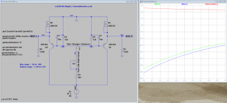
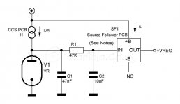
Here is the ccs circuit, source follower isn't used in this applicationstays good but if you leave output tubes in & take a driver out it's also ok
Attachments
- Home
- Amplifiers
- Tubes / Valves
- Voltage Regulator Tubes