The blue LED in my Yaqin MC-100B burned out. Turns out it's a little tiny *3mm) blue LED that was directly powered by 7.5v AC - not DC - with no resistor in sight. I'd like to change it to a red 3mm LED. I'm using Current limiting Resistor calculator for leds to calculate the resistor I'll need in series, but do I use 7.5V or 3.25V as my starting point in that calculator? Because at 7.5V DC that blue LED wouldn't have lasted a second... but if I halve that, 3.25V DC is in the range of a high intensity blue LED.
Charles.
Charles.
A generic red LED will provide plenty of light when operated at 5 mA of forward current. The forward drop is typically around 1.7 V.
The series resistor is then calculated as follows: R = V/I <-> R = (Vsupply-Vf)/I, where Vsupply is the supply voltage to the LED, Vf is the forward drop, and I is the LED current.
If you were dealing with 7.5 V DC, this would be: R = (7.5-1.7)/0.005 = 1160 Ω. I'd use 1.2 kΩ (nearest standard value).
Now you're dealing with AC. This complicates things. First off, the LED is only conducting during half the AC cycle, so you need to compensate for that. Secondly, LEDs generally can't handle much reverse voltage, so you need to protect the LED against that for half the AC cycle.
If your 7.5 V is 7.5 V RMS, all you need to do for the resistor calculation is to compensate for the fact that the LED is only on for half the cycle. So let the LED conduct at twice the current:
R = (Vsupply-Vf)/(I*2) <-> R = (7.5-1.7)/(0.005*2) = 580 Ω (560 Ω is the nearest standard value).
Now you need to protect the LED against reverse voltage. You can do that by connecting a small-signal diode, such as a 1N4148, in anti-parallel across the LED. I.e. the anode of the LED goes to the cathode of the 1N4148 and vise versa.
If your 7.5 V is 7.5 V peak, you need to calculate the RMS voltage so you can use it in the equation above. With a sine wave, VRMS = Vpeak/sqrt(2).
Tom
My 7.5v AC is measured with a simple digital voltmeter. As I understand from reading some other posts on the subject, the resistor itself will help control current into the LED and I don't have to worry about the breakdown voltage and the LED overheating and burning out, even without the added diode.
Charles.
Charles.
The resistor limits diode current while conducting, but in the non-conducting half cycle the full supply voltage is across the diode junction, that's why an antiparallel diode was suggested...
Regards,
Rundmaus
Regards,
Rundmaus
The resistor limits diode current while conducting, but in the non-conducting half cycle the full supply voltage is across the diode junction, that's why an antiparallel diode was suggested...
Precisely.
Tom
FWIW, the backward diode is "wise", but it will work without it. Reverse breakdown is not a disaster, unless the dissipation gets excessive. The same resistor that limits forward current limits reverse current. While not the same (different voltages), over a huge range of likely parameters, reverse heat is not excessive.
FWIW, the backward diode is "wise", but it will work without it. Reverse breakdown is not a disaster, unless the dissipation gets excessive. The same resistor that limits forward current limits reverse current. While not the same (different voltages), over a huge range of likely parameters, reverse heat is not excessive.
While you're right that as long as you limit the reverse current, you'll be fine. Unfortunately, to protect the LED the reverse current needs to be limited to values a few orders of magnitude below the forward current. Thus, you can't rely on the series resistor to protect the LED against reverse voltage.
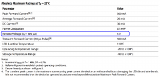
The specs below are from the Broadcom HLMP-D101, which is a pretty HeNe red (~640 nm) T-1 3/4 (5 mm) LED. I've marked the reverse voltage spec. Note that the reverse voltage is specified at a reverse current of 100 uA. Unless you know more about the LED than the manufacturer, I strongly suggest staying below the specified reverse voltage if you want the LED to last.
Tom
Attachments
I find that trial and error is usually the only way to get the series resistor correct with regard to subjective brightness and how well the LED matches other partnering equipment. Modern high brightness types can take your eyes out (figure of speech) at 100 paces with well under 1ma.
PRR is right: reverse breakdown does not hurt LEDs if they can dissipate the power. However, if they are used on full power when 2.5V falls on them, 5V can be too much.
Older LEDs happily withstood reverse operation within their dissipation limits*, but more "modern" (read more efficient) devices tend to hate any reverse breakdown, even below the µA level. Which is why they come with an ESD warning, which can sometimes be ignored -or not-.
I learned it the hard way, this is not just gratuitous scare-mongering.
Reverse protection should be included as a matter of fact. Full-wave rectification is even better as it also increases the efficiency for just a few cents with 1N4148's, which are perfectly adequate for such a light task.
*and some even emitted some light under those conditions, but generally not at their reference wavelength/color
Last edited:
Reverse protection should be included as a matter of fact. Full-wave rectification is even better as it also increases the efficiency for just a few cents with 1N4148's, which are perfectly adequate for such a light task.
Agree.
Wave... Your old avatar was better than the eclipse.
You are right, the eclipse is over.
- Status
- Not open for further replies.
- Home
- Amplifiers
- Tubes / Valves
- LED powered from 7.5volts AC